23180-000 Rev A Mobile Robot LD, LD-CT Assembly Instructions 47
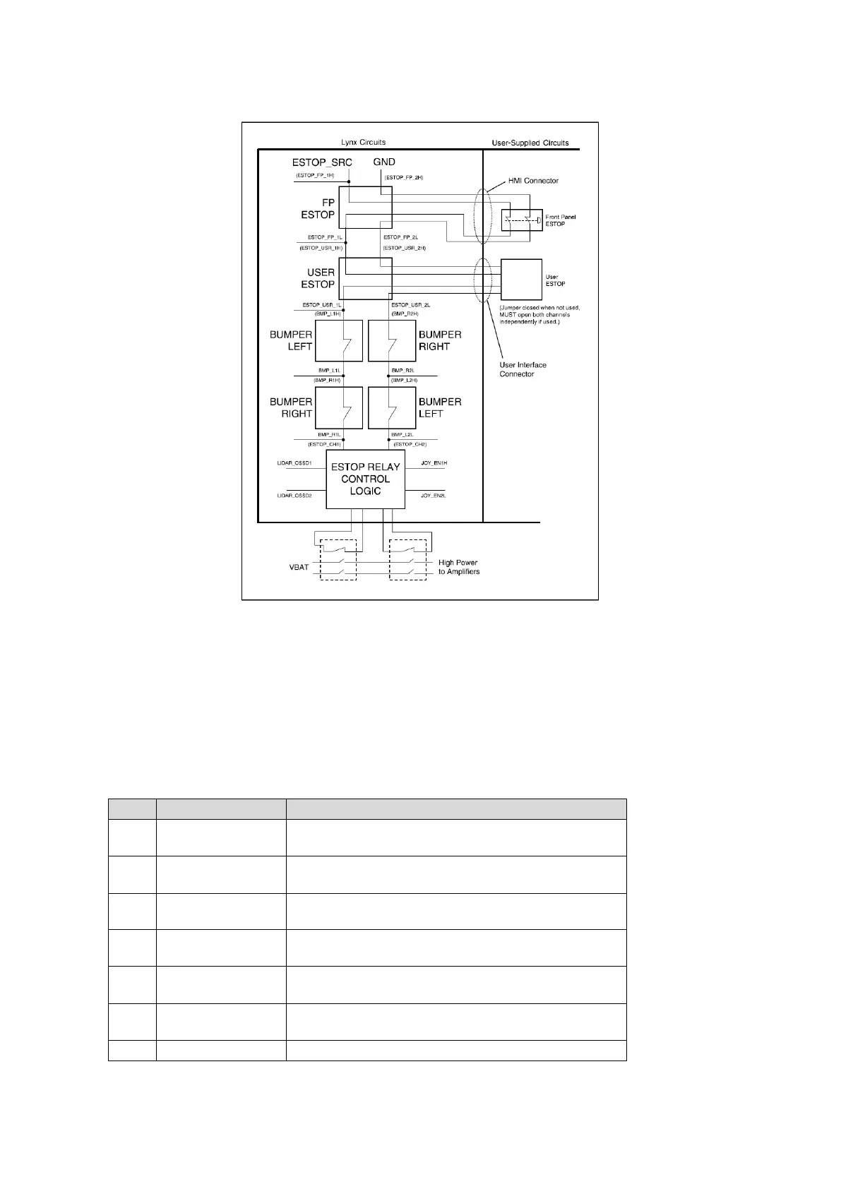
Figure 15: ESTOP Chain Diagram
User Bumper
NOTE:
Pins 1 through 3 are for a front-mounted bumper, 4 through 6 are for a rear-
mounted bumper.
Connector type: Mini-Fit® 4 x 2
Use: Optional bumper for payload structure
Short to ESTOP_SRC to signal bumper hit
Front left bumper sensor.
Short to ESTOP_SRC to signal bumper hit
Front center bumper sensor.
Short to ESTOP_SRC to signal bumper hit
Front right bumper sensor.
Short to ESTOP_SRC to signal bumper hit
Rear right bumper sensor.
Short to ESTOP_SRC to signal bumper hit
Rear center bumper sensor.
Short to ESTOP_SRC to signal bumper hit
Rear left bumper sensor.
12 V ESTOP Source Output @ 10 mA