2-19
2 System Components
MicroHAWK F320-F / F330-F / F420-F / F430-F Smart Camera User Manual
2-4 Hardware Configurations
2
2-4-1 Check Hardware and Connect the System
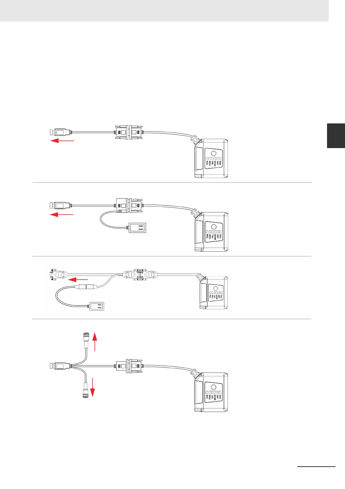
MicroHAWK F420-F
• Mount the camera securely in its stand (not supplied).
• Mount the camera as required by the application.
• Connect the integrated corner-exit cable to the MicroHAWK F420-F.
• Connect the accessory USB cable to the integrated corner-exit cable.
• Connect the USB Type A side of the USB cable to the host.
• Connect the power cable into the power source.
F420-F with DB15 to BUS Power USB Type A
F420-F with DB15 to Ext. Power/USB Type A
Integrated
Corner-Exit
Cable
Accessory USB
Cable to Host
To Host
To Host
Integrated
Corner-Exit
Cable
Accessory USB
Cable to Host
Power Supply
Note: BUS-powered cable delivers reduced illumination –
approximately 30% less brightness.
F420-F with DB15 to Ext. Power/RS-232
Power
Supply
To host
Integrated
Corner-Exit
Cable
F420-F with DB15 to Ext. Power/USB, I/O
To
Trigger
Accessory
USB Cable
to Host
Integrated
Corner-Exit
Cable
To
Power
Supply

 Loading...


