4 Screen Creation
4-14
NB-series Programmable Terminals Startup Guide Manual(V109)
User should use this method to create totally 7 frames for this project, the frames ID and names
are listed as below:
2
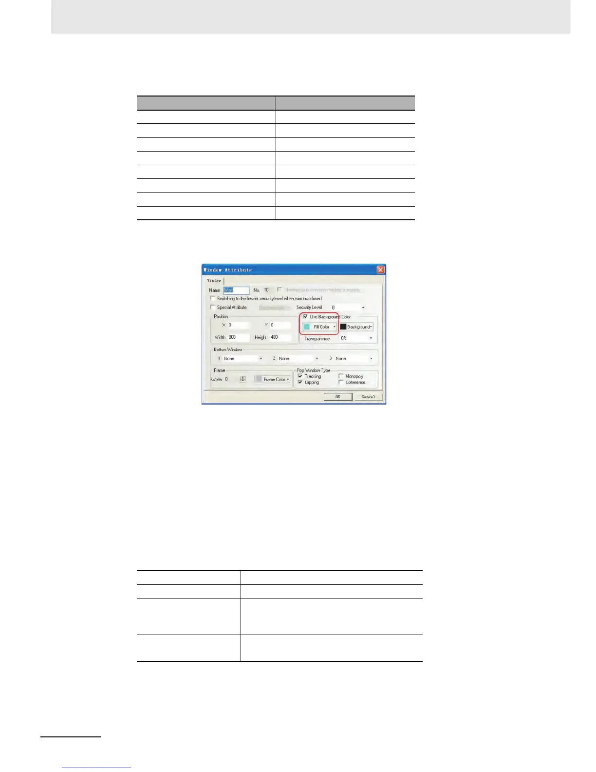
Double-click “Wait” window to eject [Window Attribute], select “User Background Color” and set
“Fill Color” to “lightCyan”.
z Bit State Setting Component
1
Bit State Setting component for switching to the maintenance screen
The Bit State Setting component on the upper left corner is used for switching to the
maintenance screen ([6 Check 1] screen).
Function: The ladder programs of CP1E will switch the screen to [6 Check 1] after pressing it to
set W0.02 to be ON. The Function Key is set transparent and will not function until being
pressed for 3 seconds for the purpose of avoiding being pressed accidentally.
Select [Bit State Setting component] from [PLC Parts], drag it to the design window after
selecting it with a single-click.
The attribute settings are:
Frame ID Frame Name
10 Wait
11 Open
12 Close
13 Stop
14 Fully Open
15 Check1
16 Check2
17 Check3
Write Address W0.02
Bit State Setting Types On
Graphics Use the vector graphic:
Dashed.vg (A vector graphic created by user,
which is a light cyan rectangle)
Control Setting
(Security Setting)
Minimum press time 3s
 Loading...


