3-30
• Use ground lines with a minimum thickness of 3.5 mm
2
, and arrange the wiring so that the ground lines
are as short as possible.
• If no-fuse breakers are installed at the top and the power supply line is wired from the lower duct, use
metal tubes for wiring and make sure that there is adequate distance between the input lines and the
internal wiring. If input and output lines are wired together, noise resistance will decrease.
• No-fuse breakers, surge absorbers, and noise filters should be positioned near the input terminal
block (ground plate), and I/O lines should be isolated and wired using the shortest distance possible.
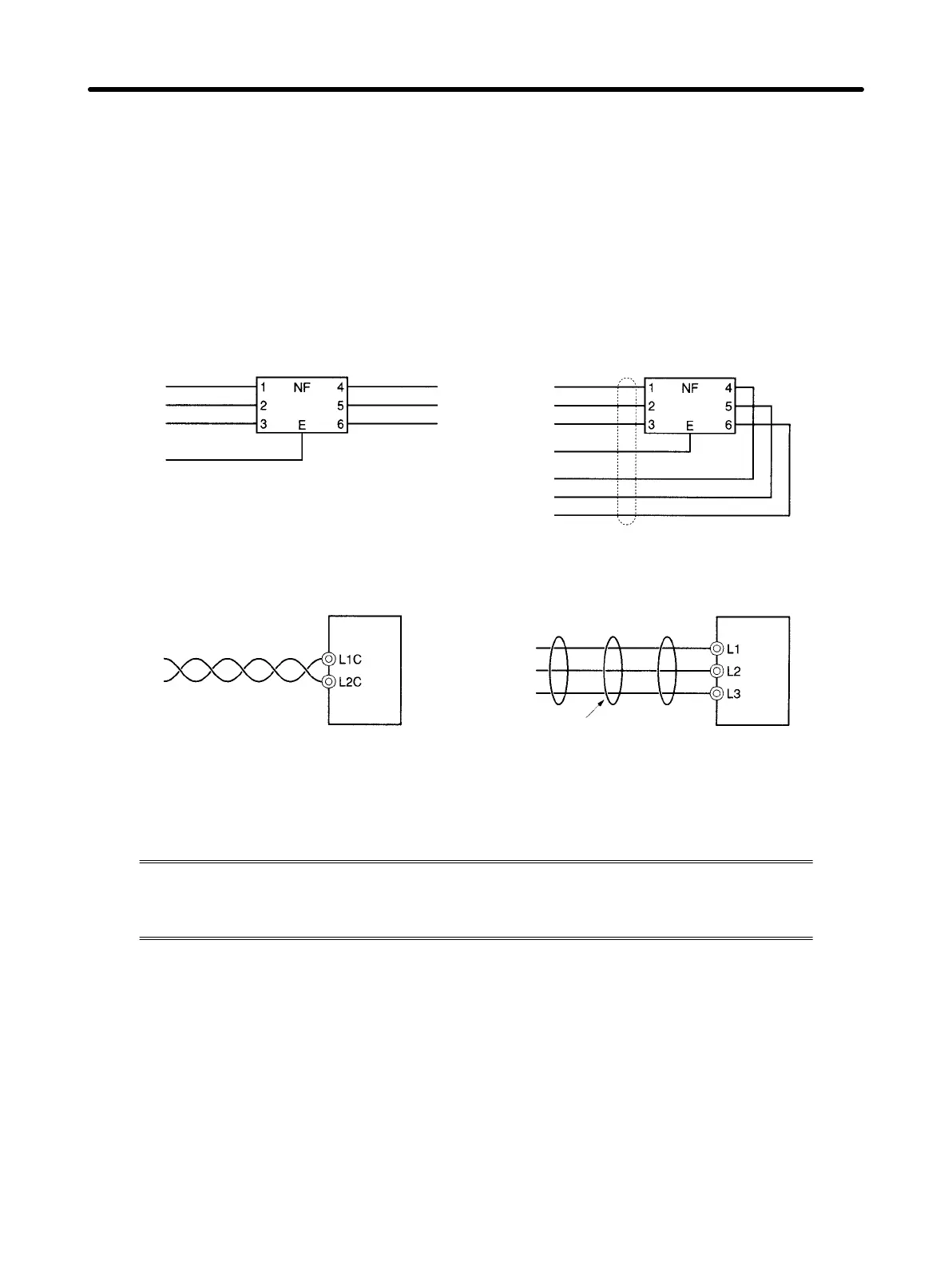
• Wire the noise filter as shown at the left in the following illustration. The noise filter should be installed
at the entrance to the control box whenever possible.
Correct: Separate input and output WRONG: Noise not filtered effectively
AC output
AC input
Ground
AC input
AC output
Ground
• Use twisted-pair cables for the power supply cables whenever possible, or bind the cables.
Driver
Binding
or
Driver
Correct: Properly twisted Correct: Cables are bound.
• Separate power supply cables and signal cables when wiring.
H Control Box Structure
If there are gaps in the control box from cable openings, operating panel installation
holes, gaps around the door, and so on, it may allow electric waves to penetrate. In order
to prevent this from occurring, take the measures described below.
D Case Structure
• Construct the control box case of metal, and weld the joints between the top, bottom, and sides so that
they will be electrically conductive.
• For assembly, strip the paint off of joined areas (or mask them during painting), to make them electri-
cally conductive.
• If gaps are opened in the control box case when tightening down screws, make adjustments to prevent
this from occurring.
• Do not leave any conducting part unconnected.
System Design and Installation
Chapter 3

 Loading...


