Chapter 4: Operation
4.1 Connectors and Indicators
1
2
18
17
16
15
14
13
12
11
10
9
8
7
6
5
4
3
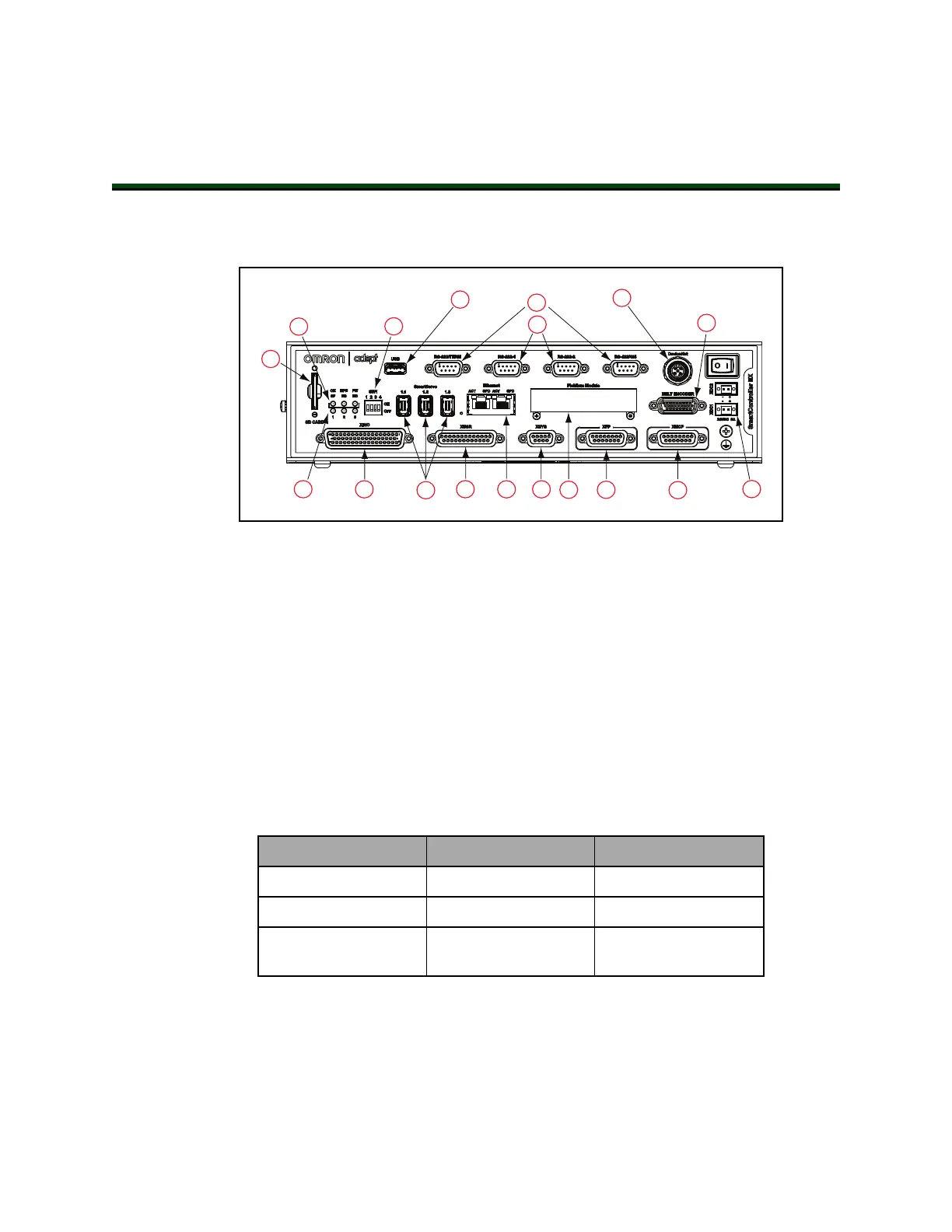
Figure 4-1. SmartController EXConnectors and Indicators
All of the connectors on the SmartController EX motion controller use standard-density spa-
cing, D-subminiature connectors. For customization purposes, the user needs to provide con-
nectors of the appropriate gender and pin count, or purchase optional factory-supplied cables.
1.
SD Card Slot
See Installing an SD Card on page 21.
2.
Top Three Status LEDs
The top three two-color LEDs indicate diagnostic test, power control, and com-
munication status.
Table 4-1. Controller LEDs
LED Green Indicates Red Indicates
OK/SF System OK System Fault
HPE/ES High Power Enabled E-Stop Open
FW/HD SmartServo Con-
nection
Read / Write from SD
card
During system bootup, the red OK / SF and HPE / ES LEDs are lit and the red
FW / HD LED blinks. After system bootup, the OK / SF LED should show green.
If the HPE / ES LED shows red, the E-Stop circuit is open. During SD card reads
and writes, the FW / HD LED pulses red. When a robot is connected on one of
the SmartServo ports, the FW / HD LED shows green.
11069-000 Rev. H SmartController EX User's Guide 27