34 SmartController EX User's Guide 11069-000 Rev. H
4.4 Configuring the SmartController
RS-232 Connectors
All three types of RS-232 connectors are 9-pin DB9 male (standard PC) connectors. The user-
supplied cable to connect to the RS-232 connectors should be a DB9, F/F, null-modem data-
transfer cable. The pin assignments are the same for all three connectors and are shown in the
following table.
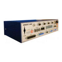
Table 4-3. RS-232 Connector Pin Assignments
Pin RS-232-1 & -2 RS-232 / Term
Signal Type Signal Type
1 Reserved - N/C -
2 RXD Input RXD Input
3 TXD Output TXD Output
4 Reserved - N/C -
5 GND Ground GND Ground
6 Reserved - N/C -
7 RTS Output RTS Output
8 CTS Input CTS Input
9 Reserved - N/C -
These ports support the RTS and CTS signals used for hardware handshaking (also known as
modem control). By default, these signals are not enabled. To configure hardware handshaking
and other communication parameters, use the eV+ FSET program instruction. The eV+ des-
ignations for these ports, when referenced in the eV+ ATTACH or FSET instructions, are
shown in the following table.
NOTE: To configure the port speed and other communications parameters, use
the eV+ FSET program instruction.
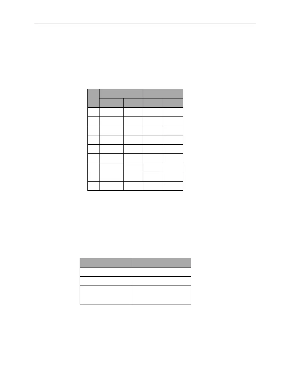
Table 4-4. Serial Connectors and eV+ Designations
Connector eV+ Designation
RS-232 / Term SERIAL:0
RS-232-1 SERIAL:1
RS-232-2 SERIAL:2
RS-422 / 485 SERIAL:3
RS-422 / 485 Connector
The RS-422 / 485 connector is a 9-pin DB9 male connector. The pin assignments are shown in
the following table. RS-422 is a point-to-point protocol for connecting to a single destination.