Chapter 4: Operation
This port can also be configured as a multidrop port (RS-485).
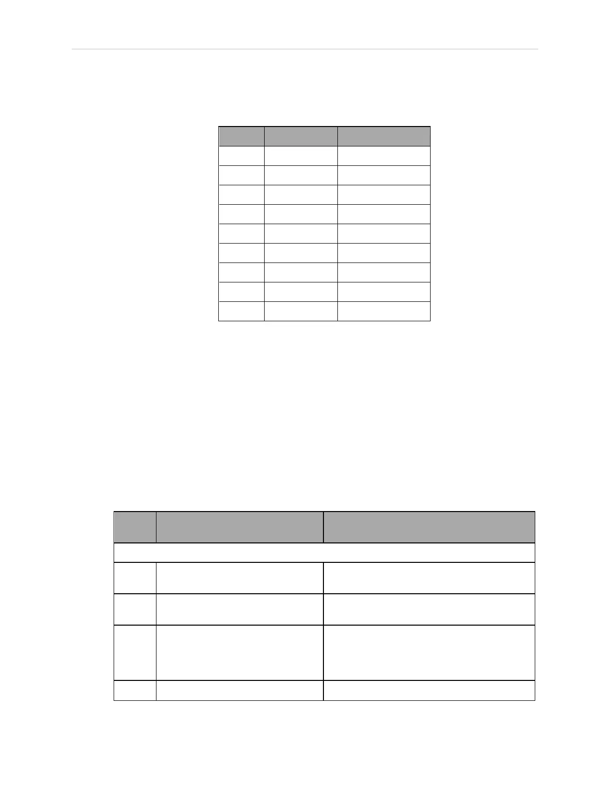
Table 4-5. RS-422 / 485 Connector Pin Assignments
Pin Signal Type
1 N/C
2 RXD+ Input
3 TXD+ Output
4 TXD- Output
5 GND Ground
6 RXD– Input
7 N/C
8 EXPIO_5V Output
9 GND Ground
To change the configuration of the RS-422 / 485 port, see Configuring Serial Ports on page 33.
See the previous table for the eV+ designation when referenced in the eV+ ATTACH or FSET
instructions.
4.5 Connecting User-Supplied Safety and Power-Control Equipment
The user-supplied safety and power-control equipment connects to the system through the
XUSR and XFP connectors on the controller. The XUSR connector (25-pin) and XFP (15-pin)
connector are both female D-sub connectors located on the front panel of the controller. Refer to
the following table for the XUSR pin-out descriptions. Refer to the table Contacts Provided by
the XFP Connector on page 37 for the XFP pin-out descriptions. See the figure CAT-3 E-Stop Cir-
cuit on XUSR and XFP Connectors on page 39 for the XUSR wiring diagram.
Table 4-6. Contacts Provided by the XUSR Connector
Pin
Pairs
Description Comments
Voltage-Free Contacts Provided by Customer
1, 14 User E-Stop CH 1 (mushroom push-
button, safety gates, etc.)
N/C contacts, Shorted if NOT Used
2, 15 User E-Stop CH 2 (same as pins
1, 14)
N/C contacts, Shorted if NOT Used
3, 16 Line E-Stop (used for other robot or
assembly line E-Stop inter-
connection. Does not affect E-Stop
indication (pins 7, 20))
N/C contacts, Shorted if NOT Used
4, 17 Line E-Stop (same as pins 3, 16) N/C contacts, Shorted if NOT Used
11069-000 Rev. H SmartController EX User's Guide 35