Appendix BSpecifications
125
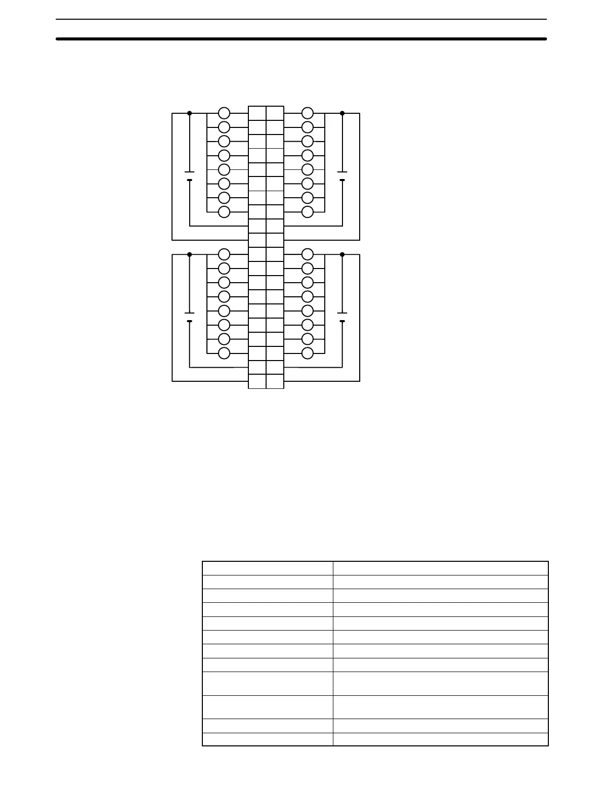
Terminal Connections
I/O word “m+1”I/O word “m”
L L
1
L
0
A
1
2
2
3
3
4
4
5
5
6
6
7
7
8
9
0
1
1
2
2
3
3
4
4
5
5
6
6
7
7
8
COM
9
B
L
L L
L L
L L
L L
L L
L L
L L
+
4.5 to 26.4 VDC
COM
+
10 10
11
12
13
14
15
16
18
11
12
13
14
15
16
17
18
19
20
19
20
17
8
9
10
11
12
13
14
15
COM
L
L
L
L
L
L
L
+
8
9
10
11
12
13
14
15
COM
L
L
L
L
L
L
L
+
Note 1. I/O word “m” is determined by the I/O number setting (m = IR 030 + 2 × I/O number).
2. When the fuse blows, the F indicator lights and the error flag in AR 02 corresponding to the I/O number is
turned ON. I/O numbers 0 to 9 correspond to AR 0205 to AR 0214.
3. The interruption of power from the external power supply is treated the same as a fuse blowout.
4. Connect power supply wiring to every COM terminal, even though the COM terminals are connected
internally.
5. When wiring output circuits, be sure to use the correct polarity for the external power supplies. Wiring
with incorrect polarity may result in erroneous operation of the load.
Transistor Output Unit C200H-OD219 (64 Points)
Max. Switching Capacity 16 mA 4.5 VDC to 100 mA 26.4 VDC (see below)
Min. Switching Capacity None
Leakage Current 0.1 mA max.
Residual Voltage 0.8 V max.
ON Response Time 0.1 ms max.
OFF Response Time 0.4 ms max.
No. of Circuits 2 (32 points/common)
Internal Current Consumption 270 mA 5 VDC max.
Fuses Two 3.5 A fuses (1 fuse/common)
The fuses are not user-replacable.
Power for External Supply 220 mA 5 to 24 VDC±10% min.
(3.4 mA × number of ON pts)
Weight 250 g max.
Dimensions D-shape
Artisan Technology Group - Quality Instrumentation ... Guaranteed | (888) 88-SOURCE | www.artisantg.com