66
When connecting TTL circuits to transistor Output Units, it is necessary to con-
nect a pull-up resistor and a CMOS IC between the two. This is because of the
residual voltage left on the transistor output after the output turns OFF.
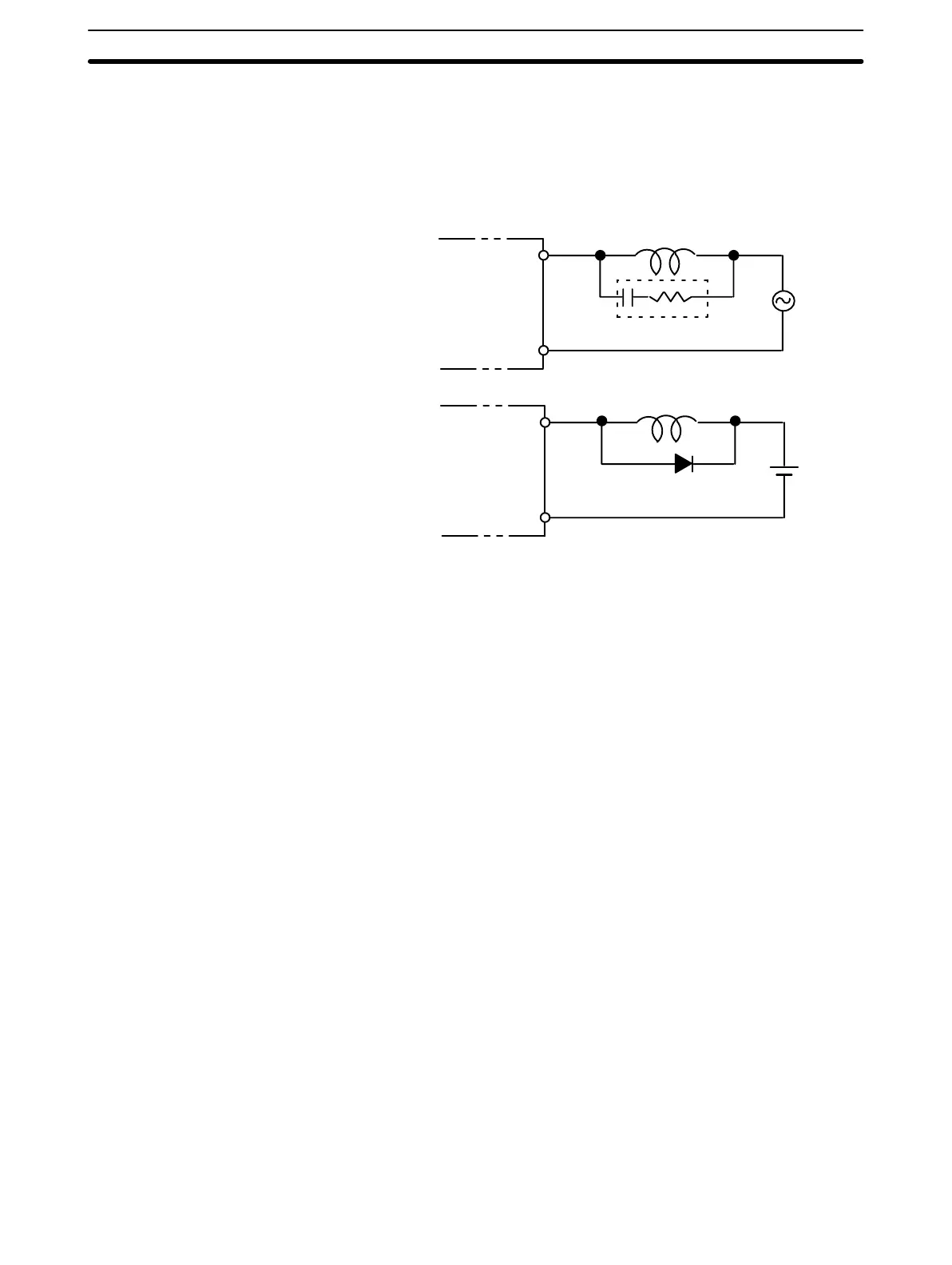
When an inductive load is connected to an I/O Unit, it is necessary to connect a
surge suppressor or diode in parallel with the load as shown below. This is so
that the back EMF generated by the load will be absorbed.
Relay Output Unit,
Transistor Output Unit
L
OUT
COM
Surge suppressor
L
OUT
COM
Relay Output Unit,
Triac Output Unit
+
Diode
7-5 Electrical Noise
Be sure to take appropriate measures when any electrical device likely to pro-
duce noise is connected to the PC as a load. Devices generating noise of more
than 1,200 V (such as electromagnetic relays and valves) require noise sup-
pression. For noise sources running off of AC power, connect a diode in parallel
with the coil of each device.
When mounting a CPU Rack and an Expansion I/O Rack together on a mounting
plate, be sure to provide a solid ground the mounting plate. The mounting plate
must be plated with a highly conductive surface in order to ensure noise immu-
nity.
Transistor Output Residual
Voltage
Inductive Load Surge
Suppressor
Electrical Noise Section 7-5
Artisan Technology Group - Quality Instrumentation ... Guaranteed | (888) 88-SOURCE | www.artisantg.com