60
6-1 Grounding
To avoid electrical shock, attach a grounded (earth ground) AWG 14 wire (cross-
sectional area of at least 2 mm
2
) to the GR terminal. The resistance to ground
must be less than 100 Ω. Do not use a wire longer than 20 m. Care must be tak-
en, because ground resistance is affected by environmental conditions such as
soil composition, water content, time of year, and the length of time since the
wire was laid underground.
The Line Ground (LG) terminal is a noise-filtered neutral terminal that does not
normally require grounding. If electrical noise is a problem, however, this termi-
nal should be connected to the Ground (GR) terminal.
PC operation may be adversely affected if the ground wire is shared with other
equipment, or if the ground wire is attached to the metal structure of a building.
When using an Expansion I/O Rack, the Rack must also be grounded to the GR
terminal. The same ground can be used for all connections.
6-2 Insulation
If a separate ground is being supplied to different Racks, Backplane Insulating
Plates must be used to insulate the Racks from each other. Insulating Plates are
supplied as an accessory (refer to Appendix B Specifications).
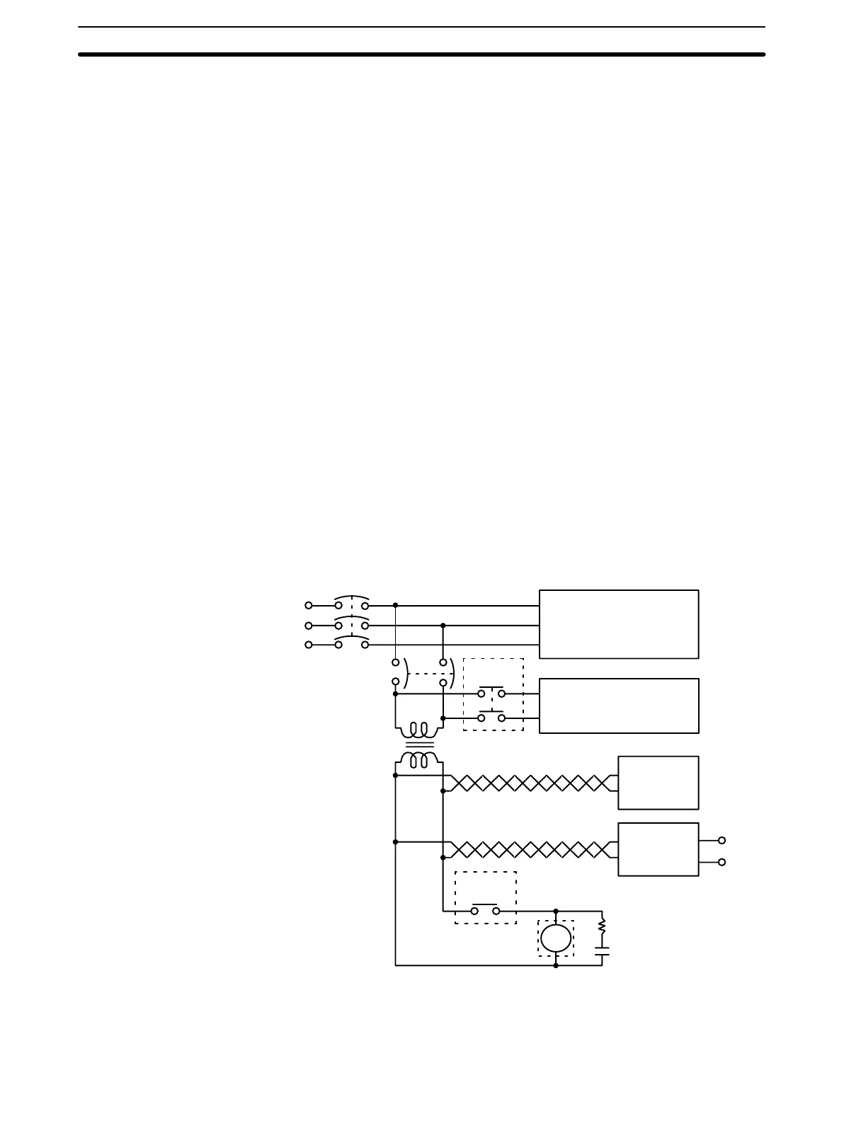
6-3 Emergency Stop
An external relay should be used to form an emergency stop circuit that turns the
power to the PC OFF in the event of an emergency. An emergency stop routine
in the PC program is not sufficient to ensure safety. The circuit shown below is an
example of an emergency stop circuit.
MCB1
Power section
Control section
CR1
MCB2
PC RUN
output
CR1
PC
DC input/output
Surge
suppressor
Twisted
Transformer
or noise filter
+
-
DC voltage
regulator
Power Failure A sequential circuit is built into the PC to handle power interruptions. This circuit
prevents malfunctions due to momentary power loss or voltage drops. A timing
diagram for the operation of this circuit is shown below.
Emergency Stop Section 6-3
Artisan Technology Group - Quality Instrumentation ... Guaranteed | (888) 88-SOURCE | www.artisantg.com