Appendix BSpecifications
132
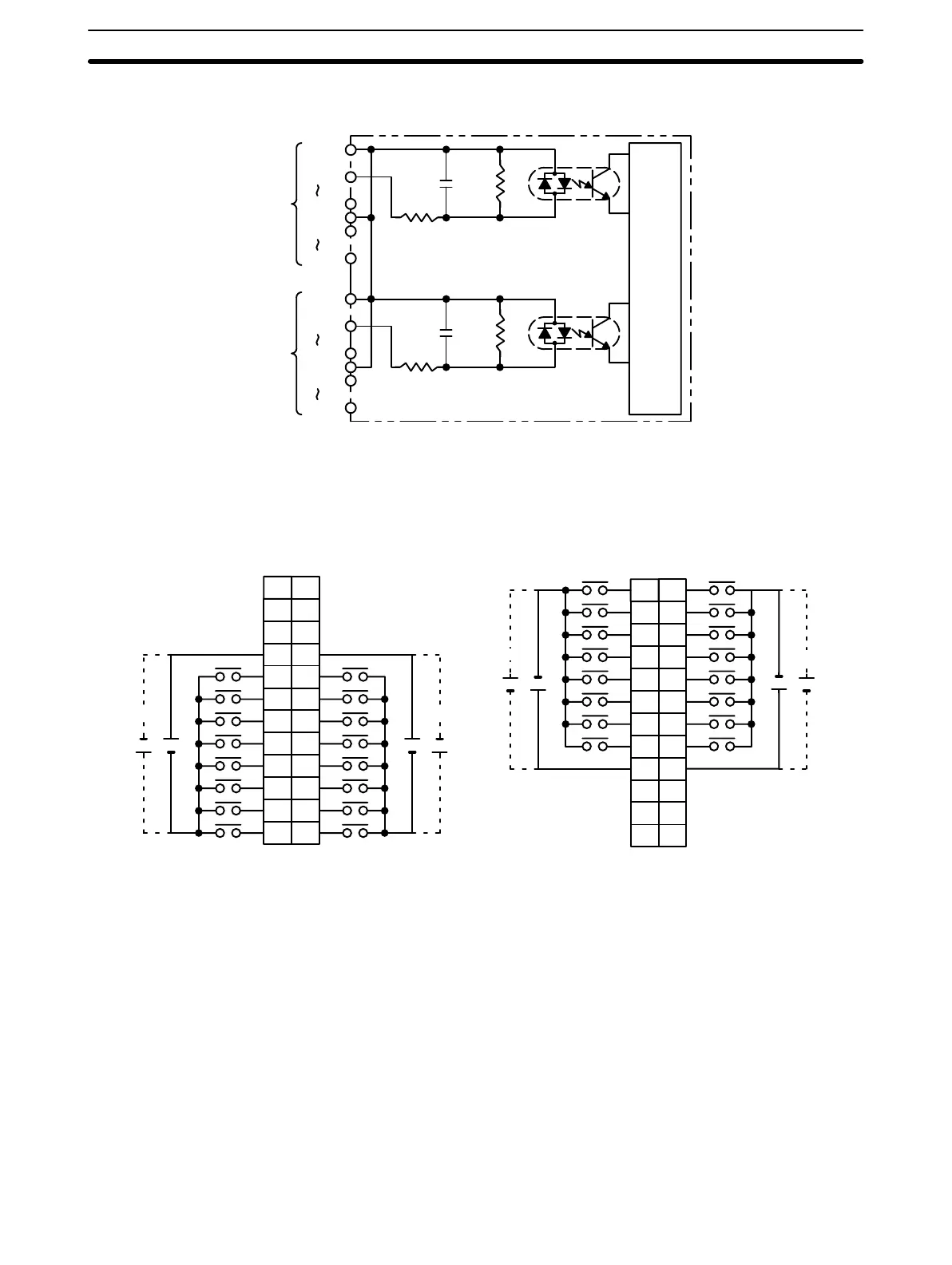
Circuit Configuration
1000 pF
620 Ω
5.6 kΩ
COM0
IN00
IN07
COM1
IN08
IN15
CN1
Internal
circuit
COM2
IN00
IN07
COM3
IN08
IN15
CN2
1000 pF
620 Ω
5.6 kΩ
Terminal Connections
I/O word “n”
CN1
I/O word “n+1”
CN2
B
1
2
3
4
5
6
7
8
9
0
1
2
3
4
5
6
7
COM0
+
NC
10
NC
11
NC
NC
8
9
10
11
12
13
14
15
COM1
+
24 VDC
AB
0
1
1
2
2
3
3
4
4
5
5
6
6
7
7
8
COM2
9
8
9
10
11
12
13
14
15
COM3
++
NC
10
NC
11
NC
NC
NC
12
+
A
1
2
3
4
5
6
7
8
9
10
11
12
NC
+
24 VDC
NC
12
NC
+
24 VDC
+
24 VDC
1
2
3
4
5
6
7
8
9
10
11
12
Note 1. I/O word “n” is determined by the unit number setting (n = IR 100 + 10 × unit number).
2. When pin 2 of the Unit’s DIP switch is ON, input points 08 to 15 in connector 2 are high-speed inputs.
3. At high temperatures, the number of inputs that can be turned ON simultaneously is limited. Refer to the
graphs on page 150 for details.
Artisan Technology Group - Quality Instrumentation ... Guaranteed | (888) 88-SOURCE | www.artisantg.com