48
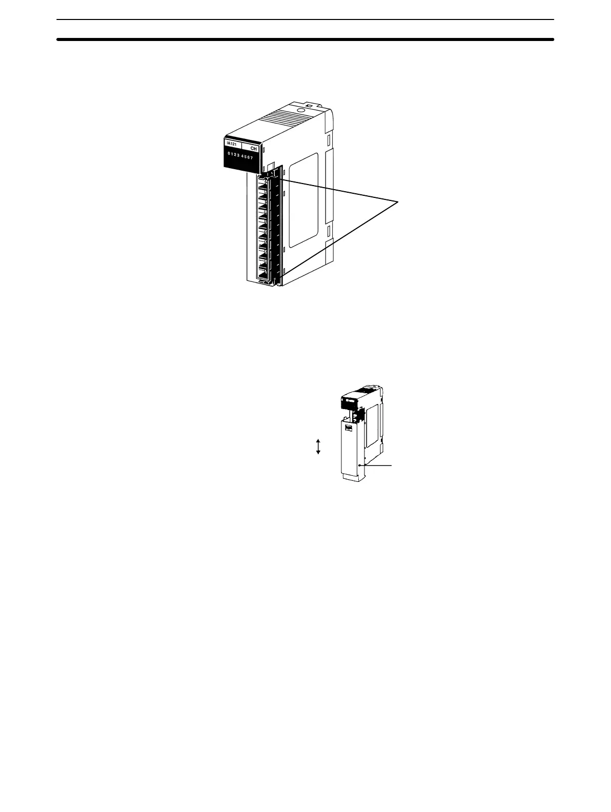
Terminal Block The terminal block of an I/O Unit can be removed by loosening the mounting
screws. You do not have to remove the lead wires from the terminal block in or-
der to remove it from an I/O Unit.
Locks for terminal block.
Unlock to remove the terminal
block from the I/O Unit. Make
sure the terminal block is
locked securely after wiring is
complete.
A C200H-COV11 Cover is provided as an I/O Unit cover for Units that use 10P
terminal block connectors. After the I/O wiring has been completed, slide the
cover up from the bottom, as shown in the illustration below.
Attach
Remove
I/O Unit cover
If a two-wire sensor is used with a 12-VDC or 24-VDC input device, make sure
that the following conditions are satisfied. Malfunctions will occur if these condi-
tions are not satisfied.
• The relationship between the PC ON voltage and the sensor residual voltage is
as follows:
V
ON
V
CC
– V
R
• The relationship between the PC ON current and the sensor control output
(load current) is as follows:
I
OUT
(min)
I
ON
I
OUT
(max)
I
ON
= (V
CC
– V
R
– 1.5 (PC internal residual voltage))/R
IN
Connect R bleeder resistance if I
ON
is less than I
OUT
(min)
.
The constant for bleeder resistance is determined by the following equation.
R (V
CC
– V
R
)/(I
OUT
(min)
– I
ON
)
Power W (V
CC
– V
R
)
2
/R 4 (margin)
• The relationship between the PC OFF current and sensor leakage current is as
follows:
I/O Unit Cover
DC Two-wire Sensor
Connection Precautions
I/O Connections Section 4-4
Artisan Technology Group - Quality Instrumentation ... Guaranteed | (888) 88-SOURCE | www.artisantg.com