70
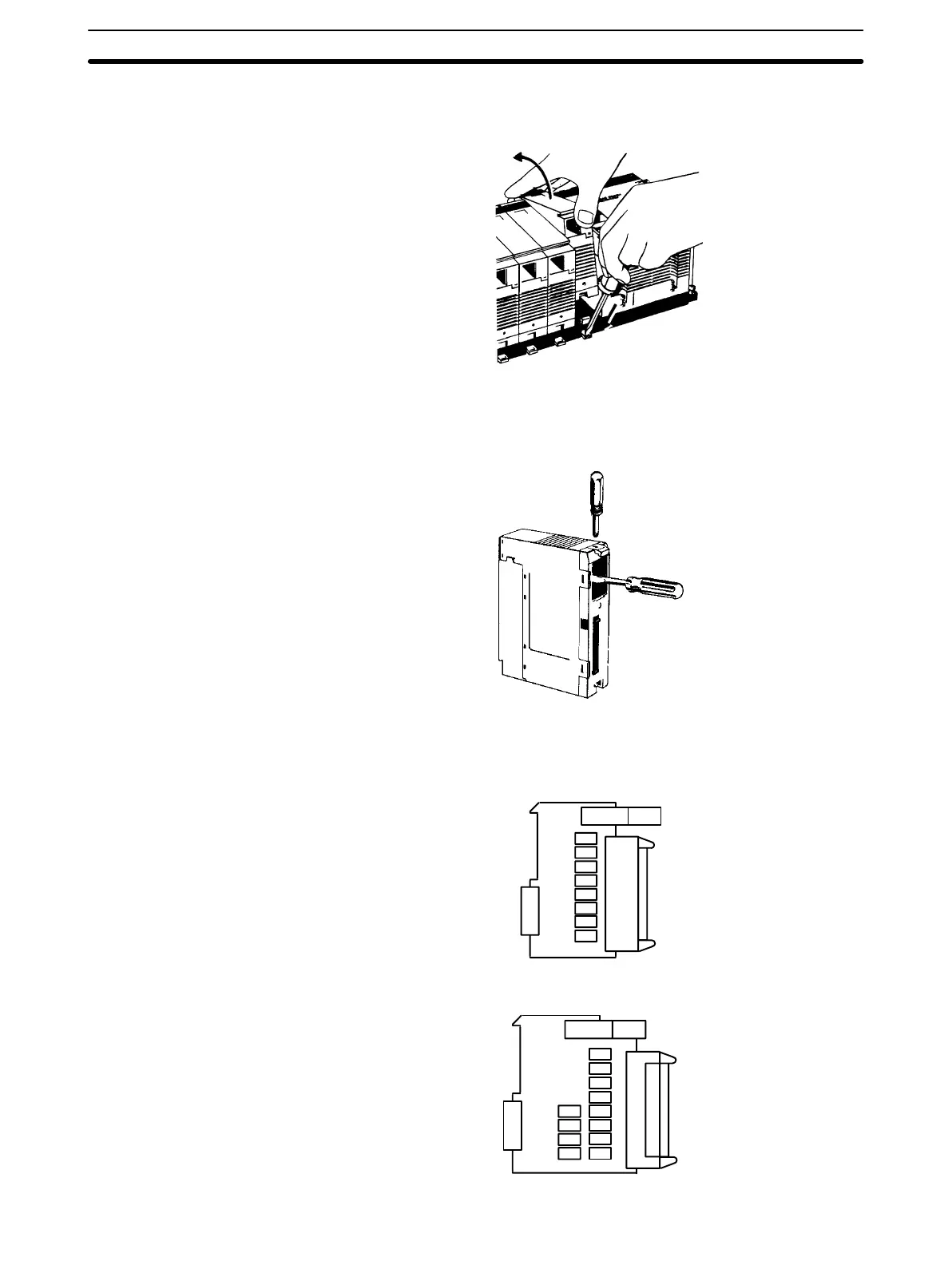
3. While pushing down the lock lever on the Backplane with a screwdriver as
shown below, remove the Output Unit.
4. Using a Phillips screwdriver, remove the screw from the top of the Unit.
5. Using a flat-blade screwdriver, detach the case from the Unit.
6. Pull out the printed circuit board. The Relays are placed on the PC boards of
individual Units as shown in the figures below.
OC221/OC224
1
2
3
4
5
6
7
0
OC222
1
2
3
4
67
0
5
8
10
9
11
Output Unit Relays Section 8-3
Artisan Technology Group - Quality Instrumentation ... Guaranteed | (888) 88-SOURCE | www.artisantg.com