EN-5
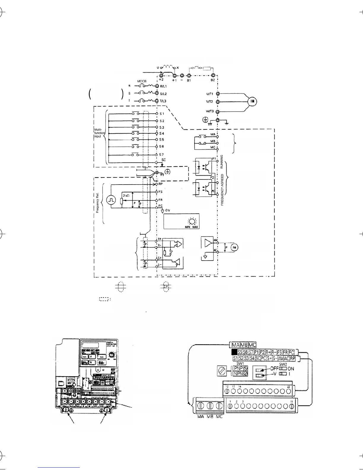
2. Wiring
Multi-function
Contact Output
250 VAC, 1 A or less *2
30 VDC, 1 A or less
Output Frequency
Grounding
Analog Monitor/Pulse
Monitor selectable
Analog Monitor
Output
0 to +10 VDC (2 mA)
Multi-function
Photocoupler Output
+48 VDC, 50 mA or less
Fault
Power Supply
For Single-phase.
Use R/L1 and S/L2.
DC Reactor
(optional)
Terminal
Overload Relay
Braking Resistor
(optional)
Short-circuit bar *1
Terminal Resistance
(1/2 W, 120 Ohm)
MEMOBUS
Communications
RS-485/422
max. 19,2 kbps
Shielded twisted-pair cable
Shielded
Pulse Train Input
Digital Operator
Frequency
Setting
Potentiometer
Reference Pulse Train
(max. 33 kHz)
Frequency Setting
Power Supply
(+12 V, 20 mA)
Frequency Setting
0 to 10 V (20 kOhm)
4 to 20 mA/0 to 20 mA (250 Ohm)
Shield connection
terminal
Forward
RUN/STOP
Reverse
RUN/STOP
External Fault
(no contact)
Fault RESET
Multi-Step
Speed Ref. 1
Multi-Step
Speed Ref. 2
JOG
Command
Only basic insulation (protective class 1, overvoltage category II) is provided for the control circuit
terminals. Additional insulation may be necessary in the end product to conform to CE
requirements.
*1. Short-circuit bar should be removed when connecting a DC reactor.
*2. Minimum permissible load: 5 VDC, 10 mA (as reference value).
Main circuit terminals
Ground terminals
Control circuit terminals
Contact Output
I43-EN-01+V7+Quick_Guide.book Seite 5 Dienstag, 25. April 2006 8:56 08