IT-4
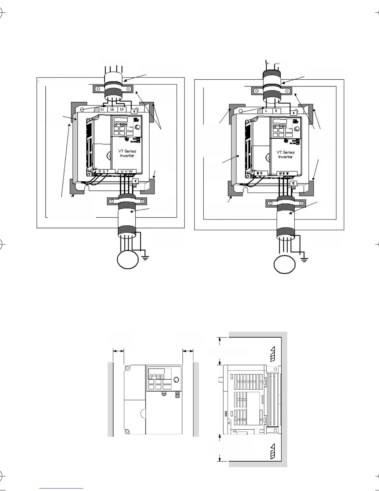
30 mm*
o più
30 mm*
o più
100 mm
o più
100 mm
o più
Aria
Aria
*: Spazio minimo per inverter da 5,5/7,5 kW
50 mm
Installazione secondo le normative EMC
CIMR-V7AZ40P2 ... 47P5 CIMR-V7AZB0P1 ... B4P0
CIMR-V7AZ20P1 ... 27P5
Dimensioni di montaggio
Cavo schermato
Collega-
menti di
messa a
terra
(eliminare
qualsiasi
traccia di
vernice)
Cavo
schermato
Piastra
metallica
di
L1 L2 L3 PE
Collegamenti di
messa a terra
(eliminare qualsiasi
traccia di vernice)
Filtro
Cavo del
motore
20 m max.
Quadro
Motore
Cavo schermato
Collegamenti di
messa a terra
(eliminare
qualsiasi
traccia di
vernice)
Cavo
schermato
Collegamenti di messa a
terra (eliminare qualsiasi
traccia di vernice)
Piastra
metallica
di montaggio
PE
N
Collegamenti
di messa a
terra (elimi-
nare qualsiasi
traccia di
vernice)
Filtro
Cavo del
motore
20 m max.
Quadro
Motore
I43-EN-01+V7+Quick_Guide.book Seite 4 Dienstag, 25. April 2006 8:56 08