EN-6
3. Control Circuit Terminals
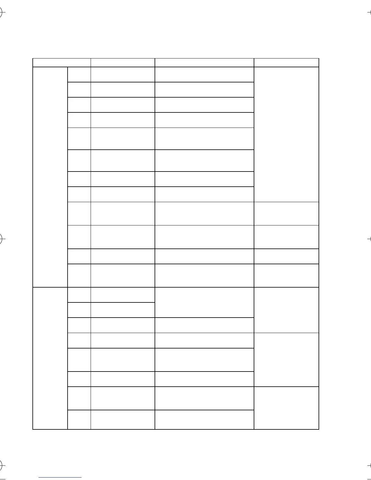
Symbol Name Function Signal Level
Input S1 Multi-function
input 1
Set by parameter n50
Default setting: Forward/Stop Photo-coupler
Insulation,
8 mA at 24 VDC
Note: NPN is the
default setting for
these terminals.
No external power
supply is required.
Refer to
connections
shown on the
following page.
S2 Multi-function
input 2
Set by parameter n51
Default setting: Reverse/Stop
S3 Multi-function
input 3
Set by parameter n52
Default setting: External fault.
S4 Multi-function
input 4
Set by parameter n53
Default setting: Fault Reset.
S5 Multi-function
input 5
Set by parameter n54
Default setting: Multi-stop
speed reference 1
S6 Multi-function
input 6
Set by parameter n55
Default setting: Multi-stop
speed reference 2
S7 Multi-function
input 7
Set by parameter n56
Default setting: JOG command
SC Sequence input
common
Common for S1 through S7
RP Master speed
reference train
input
Pulse train input signal Max. 33 kHz
FS Frequency
Reference power
supply
DC power supply for frequency
reference setting
20mA at 12 VDC
FR Frequency
Reference Input
Input terminal for frequency
reference setting
0 to10VDC 20kΩ
FC Frequency
Reference
common
Common for frequency
reference use
4 to 20 mA
0 to 20 mA
Output MA Multi-function
output: NO Set by parameter n57
Default setting: Fault
Relay output
1A max. at 30
VDC and 250 VAC
MB Multi-function
output: NC
MC Multi-function
output common
Common for MA and MB use
P1 Photo-coupler
output 1
Set by parameter n58
Default setting: RUNNING Photo-coupler
output , 50A max
at +48VDC
P2 Photo-coupler
output 2
Set by parameter n59
Default setting:
FREQUENCY AGREED
PC Photo-coupler
output common
Common for P1 and P2
AM Analogue Monitor
output
Set by parameter n65
Default setting:
output frequency
2mA max. at 0 to
10VDC.
AC Analogue Monitor
common
Common for AM use
I43-EN-01+V7+Quick_Guide.book Seite 6 Dienstag, 25. April 2006 8:56 08