6
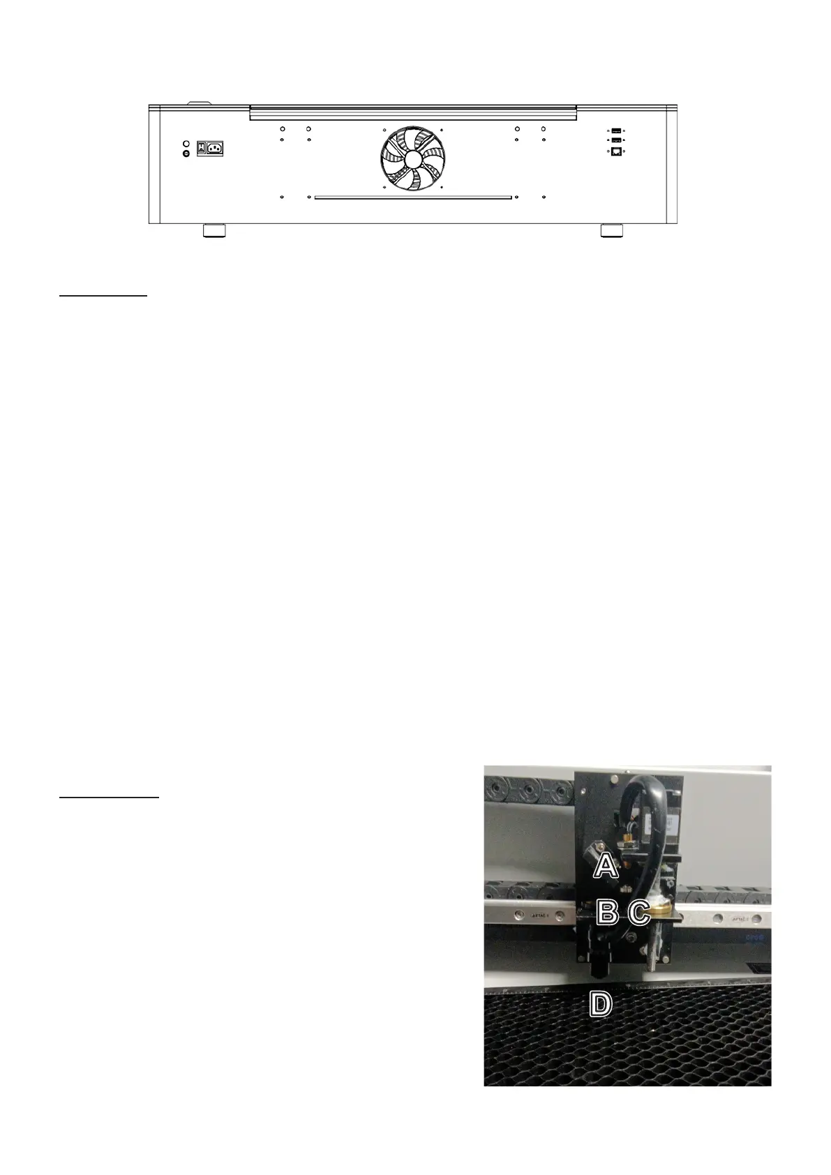
Rear View
A. Beam Attenuator—This dial provides a master power control for your engraver. It should be turned
completely clockwise to enable your software to use the engraver’s full power range.
B. Remote Interlock Connector—This port functions as a second key necessary to activate the laser tube.
Insert the provided switch to enable the laser or remove it to completely disable the laser.
C. Power Switch—This switch turns on the engraver’s mainboard, cooling system, LED lighting, and wireless
card and places the exhaust fan and air assist into standby mode, ready to activate with the laser. It
should always be turned off between sessions.
D. Power Socket—This socket connects to your main power supply and grounds your machine’s electronic
components.
E. Exhaust Fan—This fan pulls out gases and airborne debris from the workbed, sending it through your
vent to a window or air purifier.
F. Rear Pass-Through—This door can be unsealed to allow larger pieces of material to be fed into or across
the workbed. Additional care must be taken to avoid exposure to the laser beam and its reflections when
it is open.
G. Camera Port—This USB port connects the engraver’s camera to your control computer and engraving
software.
H. Computer Port—This USB port connects the engraver’s mainboard to your control computer and
engraving software.
I. Ethernet Port—This port allows a fast connection between the engraver’s mainboard and your control
computer either directly or via the internet.
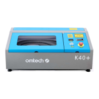
Laser Head
A. 3rd Mirror—This fixed mirror transfers the laser from
the 2nd mirror at the end of the X-axis rail downward
to the focus lens.
B. Focus Lens—This 15.5 mm lens directs and focuses the
laser beam to its point of contact with your material.
C. Air Assist—This tube provides the pressurized air from
its compressor to kill sparks and minimize dust and
gases.
D. Laser Beam—The engraving laser itself is invisible but
highly dangerous. Avoid any direct exposure to your
skin or eyes.
AAAA
CCCC
GGGG
IIII
BBBB
DDDD
FFFF
HHHH
EEEE