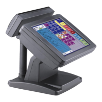
Gladius H73X 3730
59
Second LCD Panel is not functioned properly
A) Check the VGA driver of VIA LUKE (CN400) is installed properly (Please refer to the
VGA driver installation section).
B) Connect a VGA CRT monitor to the VGA2 connector, if it works, then the second LCD
panel could be defective or is not installed properly.
B-1) Please check both the VGA signal cable and second LCD power cable are
connected properly (Shut the power off before connecting the 2 above mentioned
cables).
B-2) Check the VGA cable is connected to A/D board. Or it could be defective.
B-3) Check the LCD signal cable is properly connected to A/D board and LCD panel.
Or it could be defective.
Please re-connect both ends of the LCD signal cable in the correct location. Or
replace with a new cable.
B-4) There will no backlight if the inverter is defective.
C) Check the 10 PIN VGA cable is connected to mainboard J10 and 9000PB0710
secondary I/O board CN4 properly.
D) The mainboard VGA chip could be defective.
E) The 9000PB0710 secondary I/O board could be defective.
F) If there is no power supply from the 9000PB0710 secondary I/O board, then check if the
power cable is properly connected between position CN8 of 9000PB0710 and position
CON12 of 9000PB0700. If there is still no power then the fuse “F3” on the 9000PB0710
could be defective.
Second Touch Screen is not functioned properly
A) Check BIOS settings, COM4 needs to be “Enabled”. The correct settings are “2E8h” and
“IRQ11”.
B) Check there are no conflicts between COM4 IRQ11 and any other devices.
C) Check the ELO driver has been properly installed. Or try to re-install again (Please refer
to the ELO driver installation).
D) Check the ELO controller on COM4 has been detected during the ELO driver installation.
If yes, then Check the flat cable from the ELO touch screen has been properly connected to
the ELO controller.
(Attention: Pin1 mark should be on the same side as the ELO controller).
E) Check the ELO controller Green LED is blinking.
If no, there is no DC+5V support for the ELO controller from the mainboard.
E-1) Check the 9000PB0270 secondary I/O board JP1 and JP2 jumper settings. The
correct jumper settings for the second Touch screen are:
JP1 PINs 2-3 shorted.
JP2 PINs 1-3, PINs 2-4 shorted.
E-2) Check the RJ45 cable from the second Touch panel is connected properly to the
COM4/VFD port.
E-3) Check the COM4 cable is properly connected between 9000PB0270 secondary
I/O board CN7 and mainboard J43.