Setup and Installation
ONePlus UPS User Instruction Manual 11
Connections
Before beginning, shut down and unplug the
equipment to be protected. DO NOT make any
connections or attempt to use any of the equipment
until all the following connection instructions have
been reviewed and completed.
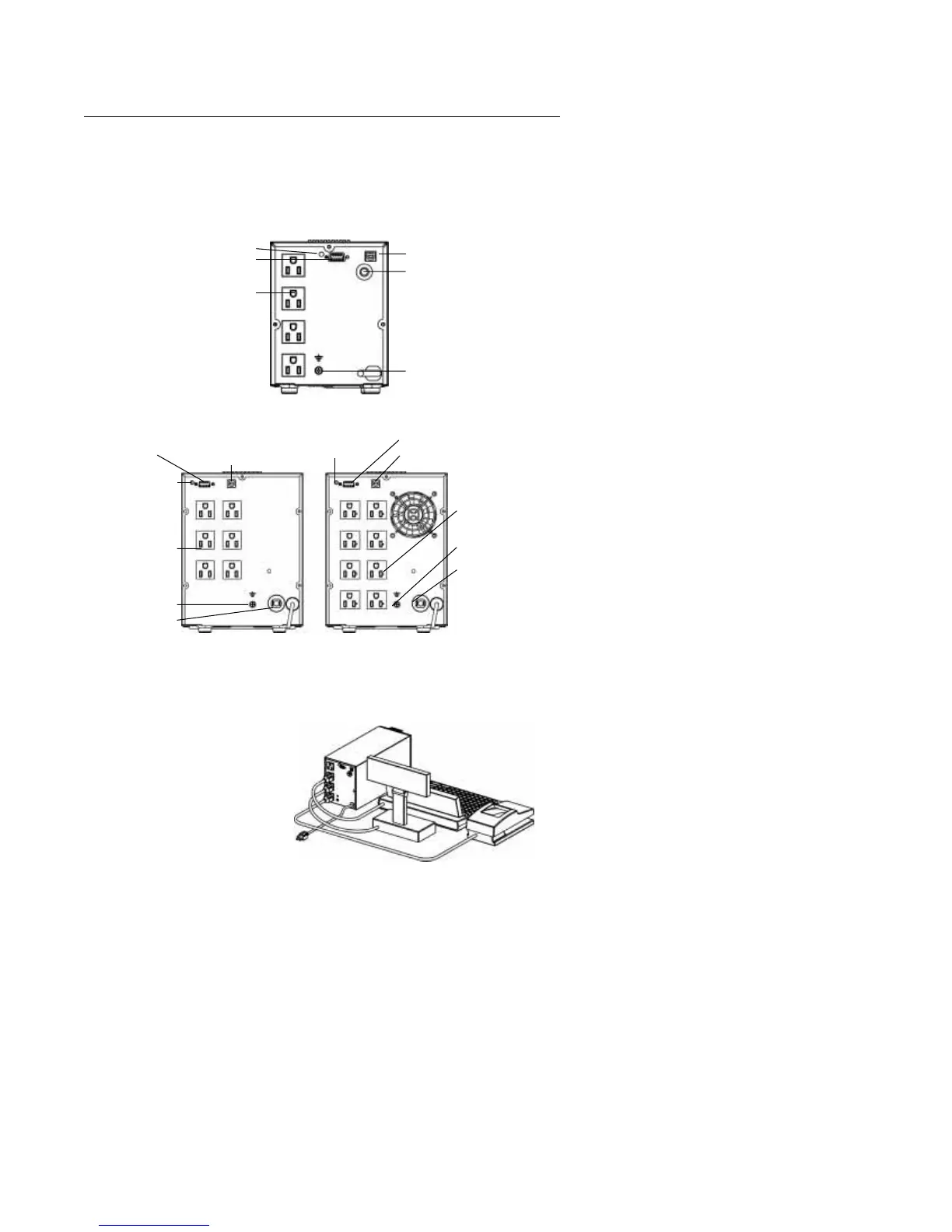
fig. 2: 250 and 400 VA ONePlus UPS Back Panels
fig. 3: 600 and 1000 VA ONePlus UPS Back Panels
fig. 4: Typical UPS Installation
Site Wiring Fault Indicator
Serial Communication Port
Four 5-15 Receptacles
USB Communication Port
Input Circuit Breaker
Ground Lug
USB Communication Port
Six
5-15 Receptacles
Serial Communication Port
USB Communication Port
Serial Communication Port
600 VA ONePlus 1000 VA ONePlus
Eight 5-20
(for 5-15R or 5-20Rs)
Ground Lug
Input Circuit Breaker
Ground Lug
Input Circuit Breaker
Site Wiring
Fault Indicator
Site Wiring
Fault Indicator
e
r
ng
Fault Indicator
Connect communication cable
from Terminal to UPS (optional)