Setup and Installation
14 ONePlus UPS User Instruction Manual
Self-Test
The UPS performs a self-test when it is first plugged
in and turned ON. A green LED indicates normal AC
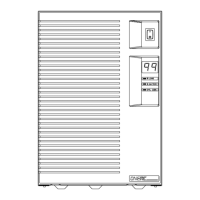
output. The three LEDs on the front panel will
indicate the status. A blinking yellow LED shows the
battery is being charged. The UPS will continuously
monitor the condition of the battery. If the battery
cannot be charged, is disconnected or takes too long
to charge, a code is represented in the LED Display.
NOTE:
The System Code Status Chart on the back of
the UPS (and on page 27 of this manual) provides a
quick reference for interpretation of the system status
LEDs.
To initiate a self-test, press and hold the button
for five seconds. If the UPS finds a problem, an LED
indicates where the problem is. For more about the
LED indicator lights, see Troubleshooting on page
28.
NOTE:
Be sure the batteries are fully charged and
the UPS is not in Battery-mode before initiating the
self-test.
Indicators and
Alarms
Battery-Mode
If the AC input power source to the UPS rises too
high, too low or fails, the UPS will switch to the
internal inverter to deliver power to the outlet
receptacles from the batteries. The LEDs will
indicate that the UPS is on battery (see System Code
Status Chart on page 27). An audible alarm will also
sound every minute.
Low Battery
When the battery voltage falls to a predetermined
level, the audible alarm will sound continuously and
the green and yellow LEDs will blink. If the UPS
continues to operate in this mode for two minutes or
more, the UPS will shutdown and remove power
from the output receptacles.
When AC power returns, the UPS will return to
on-line operation and the batteries will automatically
recharge.