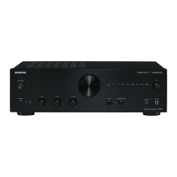
A-9000R/9070
Service Procedures
1.Operation check
1) Speaker relays
The relay shall be ON about 5 seconds after POWER is ON and shall be OFF immediately after POWER is OFF.
2) Voltage-detection protectors
The speaker relay is OFF immediately after D.C. 3V is put at MAIN IN INPUT terminal to check SP:B(L/R).
The same as above when D.C. -3v is put at each place. TEST:4-02.
3) Current-detection protectors
a) The relay shall be ON when 3 ohm load is connected to each channel under the conditions of peak-to-zero 35V output
for L,Rchannels and no load by using the INTEGRA ampifier series designated circuit with 200Hz square wave.Use
TEST:2-17 MAIN IN mode input MAIN IN.
b) The relay shall be OFF when 1.5 ohm load is connected to each channel under the conditions of peak-to-zero 35V
output for L,R channels and no load by using the the INTEGRA ampifier series designated circuit with 200Hz square
wave.
If a relay goes out, Disconnect input signal immediately.
Don't continue to do this check 3 seconds or more.
4) FL tube test (All lighting check)
Please confirm the all FL display lights by TEST MODE 'TEST-1-00'.
5) Buttons
Please confirm by TEST MODE 'TEST-1-01'.
6) DIMMER
Please push DIMMER button of Remote controller and confirm the brightness of FL display changes and the white LED
lights(A-9000R only).
7) Firmware version.
Set the test mode "0-01". Please check the Firmware version.
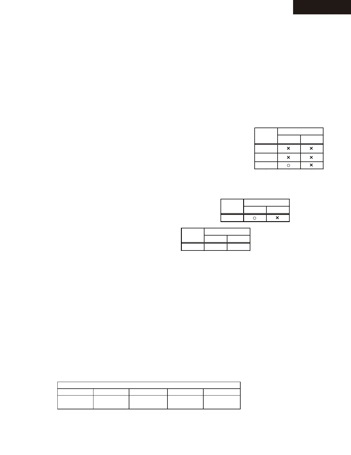
8) Adjustment and Confirmation of Destination
a) Please confirm the R1293 on the BADG-0998.
When destination is MJJ or MDC or MGR,It is nothing on the PWB.
When destination is MPP, It exist on the PWB.
b) Set the test mode "0-02".
Please check Model Number.
c) Set the test mode "0-03".
Please check Destination.
Please check the display of FL refer to right table.
9) Auto Standby (ASb) detection circuit
a) Set the test mode "4-00".
b) Confirm that the character of "ASb" is not displayed in FL display under the condition of no signal.
c) Confirm that the character of "ASb" is displayed in FL display, when "-20dBV,-14dBV, 1kHz" signal is input to Line1
Terminal.
2. To initialize the unit.
Press ON/STANDBY button in the TEST MODE, then the FL displays "CLEAR", and turn to STAND-BY mode.
Remove AC cord from INLET.
3. Initial setting
Mechanical Power Switch - ON
Phono MM/MC Switch - MC
Direct SW - OFF
White LED
TEST MODE
1)Set volume 0dB and push ON/STANDBY button while pushing down SET UP button to display "TEST-_".
2) Next, if the following keys are pushed, it becomes a each TEST MODE.
3) In the test mode, The TEST MODE number goes up if the selector knob is turned to the right.
The TEST MODE number goes down if the selector knob is turned to the left.
0 -00 1-00 2-00 3-00 4-00
NO PUSHED TREBLE - TREBLE + BALANCE L
 Loading...