ADJUSTMENT PROCEDURE
DC OFFSET ADJUSTMENT
A-933
R427
R428
C407
C403C404
C408
R401
R405
R421
9
R406
R422
C
C401C402
R402
R404 R403
2
436
R435
R437
D
C435
C436
R495
R497
R483
R484
R496
498
R651
R494 R493
C432 C431
[When]
1. Exchange the parts on the POWER AMPLIFIER PC board (NAAF-8496).
2. Exchange the POWER AMPLIFIER PC board ass'y (NAAF-8496)
[Procedure]
<Notes>
No load and No signal
1. Connect to DC voltmeter to the SPEAKER terminals.
2. Connect the power cord to the wall outlet.
3. Press the POWER switch to unit is power on.
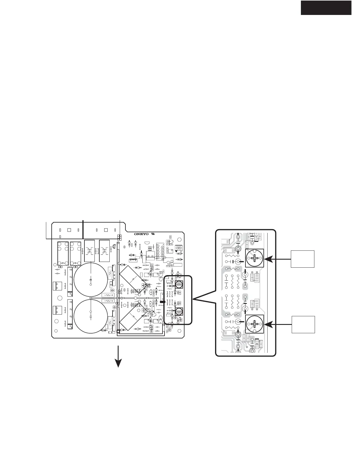
4. Adjust the trimming resistor R427 (Lch) and R428 (Rch) so that the reading of DC voltmeter becomes DC 0 +/-10 mV.
Refer to <Fig-1> .
5. Wait for 2 minutes.
6. Adjust the trimming resistor R427 (Lch) and R428 (Rch) so that the reading of DC voltmeter becomes DC 0 +/-10 mV.
Spec. : 0 +/- 10 mV
7. Press the POWER switch to unit is power off.
8. Disconnect the DC voltmeter.
9. Disconnect the power cord from the wall outlet.
R428
Rch
R427
Lch
Front side
POWER AMPLIFIER PC board
(NAAF-8496)
<Fig-1>