EasyManua.ls Logo

Onkyo HT-R495 Service Manual

Onkyo HT-R495
100 pages
To Next Page IconTo Next Page
Page #1 background imageLoading...
Page #1 background image
Published by Onkyo & Pioneer Corporation Global CS Department 2019
For details, refer to "Important Check Points for good servicing".
Service Manual
Ref.No. : 4862
HT-R495
AV Receiver
Final Issue
HT-S5910(B) = HT-R495(B) + HTP-596(B)(SKF-596(B)+SKC-594(B)+SKR-594(B)+SKW-593(B))
HT-S5915(B) = HT-R495(B) + HTP-598(K)(SKF-596(K)+SKC-594(K)+SKR-594(K)+SKW-658(B))
THIS MANUAL IS APPLICABLE TO THE FOLLOWING MODEL(S) AND TYPE(S).
Model Color Type Power Requirement Remarks
HT-R495 (B) – Black MDC AC 120 V Canada/USA
HT-R495 (B) – Black MMP AC 220 V to 240 V Europe
HT-R495 (B) – Black MMB AC 220 V to 240 V UK
HT-R495 (B) – Black MMT AC 220 V to 240 V Thailand
HT-R495 (B) – Black MMA AC 220 V to 240 V Australia/New Zealand
HT-R495
SKF-596
SKC-594
SKR-594
SKW-658
(For HT-S5915)
SKW-593
(For HT-S5910)
Question and Answer IconNeed help?

Do you have a question about the Onkyo HT-R495 and is the answer not in the manual?

Onkyo HT-R495 Specifications

General IconGeneral
Channels5.1
Signal-to-Noise Ratio (Line, IHF-A)106 dB
HDMI Inputs4
HDMI Outputs1
Dolby AtmosNo
DTS:XNo
4K Ultra HD Pass-throughYes
HDR SupportHDR10, HLG
BluetoothYes
Phono InputNo
FM/AM TunerYes
Network FeaturesNo
Radio TunerFM/AM
Weight lbs17.6
Weight kg8.0
Frequency Response10 Hz - 100 kHz
Frequency Response (Direct Mode)10 Hz-100 kHz/+1 dB, -3 dB
Total Harmonic Distortion (THD)0.08%
Total Harmonic Distortion0.08%
Input Sensitivity200 mV
Input Impedance47 kOhms (Line)
Signal-to-Noise Ratio106 dB
HDMI Version2.0
HDCP Support2.2
Dimensions (W x H x D) mm435 x 160 x 330.5

Summary

Service Manual

Applicable Models and Types

Details models and types this manual applies to.

Important Check Points for Good Servicing

Product Safety

Covers safety precautions during repair.

Adjustments

Describes the process for adjustments.

Lubricants, Glues, and Replacement Parts

Details on using specified materials.

Cleaning

Guidelines for cleaning parts.

Service Notes

Safety Warnings and Cautions

Highlights critical components, post-repair checks, and battery replacement warnings.

Parts List File Naming Convention

File Name Structure Explanation

Explains how parts list filenames are structured.

Reset and Recall Operations

Store and Recall User Preferences

Procedures to save and load user settings.

Reset Function

Steps to perform a factory reset.

Protect Mode and Diagnostic Functions

Protect Mode Explanation

Describes when the unit enters standby due to abnormal conditions.

Self-diagnostics

Operation and Problem Display

How diagnostics work and display results.

Troubleshooting and Repair Process

Confirming Protect Cause and Clearing Errors

Steps to identify the protect cause and clear information.

Canceling Self-diagnostic and Manual Execution

How to exit diagnostics and start manually.

Service Mode Entry and Information

Accessing Service Mode and Displaying Info

Instructions to enter, exit, and view service info.

Clearing Protect Data

Procedure to reset error history.

Service Information

Listening Mode Code List

List of codes for audio listening modes.

Firmware Update Preparation

Checking Versions and Preparing Files

Steps for checking versions and preparing update files.

Firmware Update Procedure (Service Mode)

Connecting USB and Selecting Modules

Initial steps for updating firmware and choosing components.

Firmware Update Execution

Starting and Completing Update

Steps to start and verify the update.

Model and Destination Settings

Verifying Model and Destination

How to display and verify model/destination.

Idling Current Check

Aging and After-check Procedures

Aging process and post-aging check steps.

Troubleshooting: No Sound

Player, TV, and Loudspeaker Issues

Troubleshooting steps for various no sound scenarios.

General Issue Resolution

Power cycle and reset steps.

Troubleshooting: No Picture

General and HDMI/Component Video Issues

Troubleshooting for common and specific video problems.

General Issue Resolution

Power cycle and reset steps.

Troubleshooting: No Power

General Power Issues and Resolution

Troubleshooting steps and general resolution.

Troubleshooting: No Sound (HDMI Input)

PCB Checkpoints for HDMI Audio

Details specific checkpoints for HDMI audio issues.

Troubleshooting: No Sound (Optical/Coaxial Input)

PCB Checkpoints for Optical/Coaxial Audio

Details specific checkpoints for optical/coaxial audio issues.

Troubleshooting: No Sound (Analog Input)

PCB Checkpoints for Analog Audio

Details specific checkpoints for analog audio issues.

Troubleshooting: No Picture (HDMI)

PCB Checkpoints for HDMI Video

Details specific checkpoints for HDMI video issues.

Troubleshooting: No Power (Component Check)

PCB Checkpoints for Power Issues

Details specific checkpoints for power supply issues.

PCB Checkpoint Details: BAAF-2690

Voltage Checks on BAAF-2690 Board

Lists specific voltage checks on the board.

PCB Checkpoint Details: BAAF-2690/BACLA-2673

Visual Damage Inspection Guidance

Instructions for visual inspection of damage.

PCB Checkpoint Details: BADIS-2672

FFC Connection and Contact Checks

How to check FFC for the BADIS-2672.

PCB Checkpoint Details: BAPRC-2695

Voltage and Signal Checks on BAPRC-2695

Lists specific checks on the board.

PCB Checkpoint Details: BAPS-2674

Power Supply and Relay Checks

Details checks for power supply and relay.

Block Diagrams: Analog Audio Processing

Analog Audio Signal Flow and Digital Audio Path

Shows how analog and digital audio signals are processed.

Block Diagrams: Video Processing

HDMI Video Signal Flow

Shows how HDMI video signals are handled.

Block Diagrams: Digital Audio & Control

System Control and Digital Audio Interfaces

Details control and audio interfaces.

ASP Section Schematic

ASP Circuit Details

Shows the schematic for the ASP section.

Amplifier Section Schematic

Amplifier Circuit Details

Shows the schematic for the amplifier stages.

Thermal Sensor Section Schematic

Thermal Sensor Circuit Diagram

Shows the schematic for the thermal sensor.

Amplifier Section Schematic: Class A

Class A Amplifier Circuit Details

Details Class A amplifier stages.

Power Supply Section Schematic

Power Supply Circuitry Overview

Shows the schematic for the power supply unit.

Display Section Schematic

Display Circuit Details

Shows the schematic for the front panel display.

Headphone Section Schematic

Headphone Circuit Details

Shows the schematic for the headphone output.

DSP Section Schematic

DSP Block Diagram and Functionality

Details the DSP processing block.

Power Supply Section Schematic Details

Voltage Regulation Circuits Diagram

Shows specific voltage regulation circuits.

HDMI Section Schematic

HDMI Interface Circuit Diagram

Shows the schematic for HDMI input/output.

DIR/DAC/BT Section Schematic

Digital Audio and Bluetooth Interfaces

Details the digital audio and Bluetooth connectivity.

MMPU Section Schematic

Main Microprocessor Unit (MMPU) Diagram

Shows the schematic for the main MCU.

VMPU Section Schematic

Video Processing Unit (VMPU) Diagram

Shows the schematic for the video processing unit.

Bluetooth Module Section Schematic

Bluetooth Module Circuit Diagram

Details the Bluetooth module schematic.

Tuner Section Schematic

Tuner Circuit Diagram

Shows the schematic for the tuner.

Packing Information and Accessories

Included Package Contents

Lists items included in the package.

Overall Exploded View and Compliance Information

Unit Component Exploded View

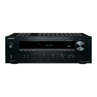
Shows a general exploded view of the unit.

FCC and IC Regulatory Compliance

Details regulatory compliance statements.

Exploded View: Rear and Amplifier Sections

Rear Panel and Amplifier Components Diagram

Shows exploded view of rear and amp parts.

Button Operation Notation Conventions

Explanation of Notation Symbols

Explains how button operations are described.

User Parameter Data Management

Store, Recall, and Reset User Preferences

Procedures for managing user settings.

Main MCU Checksum Verification

Procedure for Verifying MCU Checksum

How to verify the MCU checksum.

Key Operation Check Procedure

Step-by-Step Button Testing

Steps to test all buttons.

FL Tube and LED Check Procedure

Verifying Front Panel Indicators

Procedure to check front panel indicators.

Service Mode Entry and Data Clearing

Accessing Service Mode and Exiting

Instructions to enter, exit, and view service info.

Clearing Protect Data

How to clear protect data.

Service Mode Navigation Tree (Part 1)

Tech Support Menu and Diagnostics Options

Outlines options under Tech Support and diagnostics.

Audio and Video Menu Structures

Outlines options for audio/video sections.

Service Mode Navigation Tree (Part 2)

Video Settings and Control Parameters

Details video-related service settings.

Sales and Other Service Parameters

Covers sales and miscellaneous settings.

Service Mode: Tech Support Details

Checksum, Protect Data, and Model Check

Explains checksum, protect data, and model verification.

Hardware Status and AmpChDiag

How to check hardware status and run diagnostics.

Service Mode: Video Settings (Part 1)

FAD Mode, Dolby VDB Thru, HDMI Thru

Settings for HDCP, Dolby Vision, and HDMI standby-thru.

Power Control, TV Control, Max TMDSCR

Settings for power, TV interaction, and TMDS clock.

Service Mode: Video Settings (Part 2)

LTE 340 SC, Thru Sel Change, Pass Thru MD

Settings for scramble, selector switching, and HDMI-CEC.

Content Type Setting

Setting for content information.

Service Mode: Sales Settings

Photo Mode Usage Explanation

Explanation of the photo mode.

Related product manuals