TX-NR1030/3030/ PR-SC5530/ DTR-60.6/70.6/ DHC-80.6
OPERATION CHECK-2
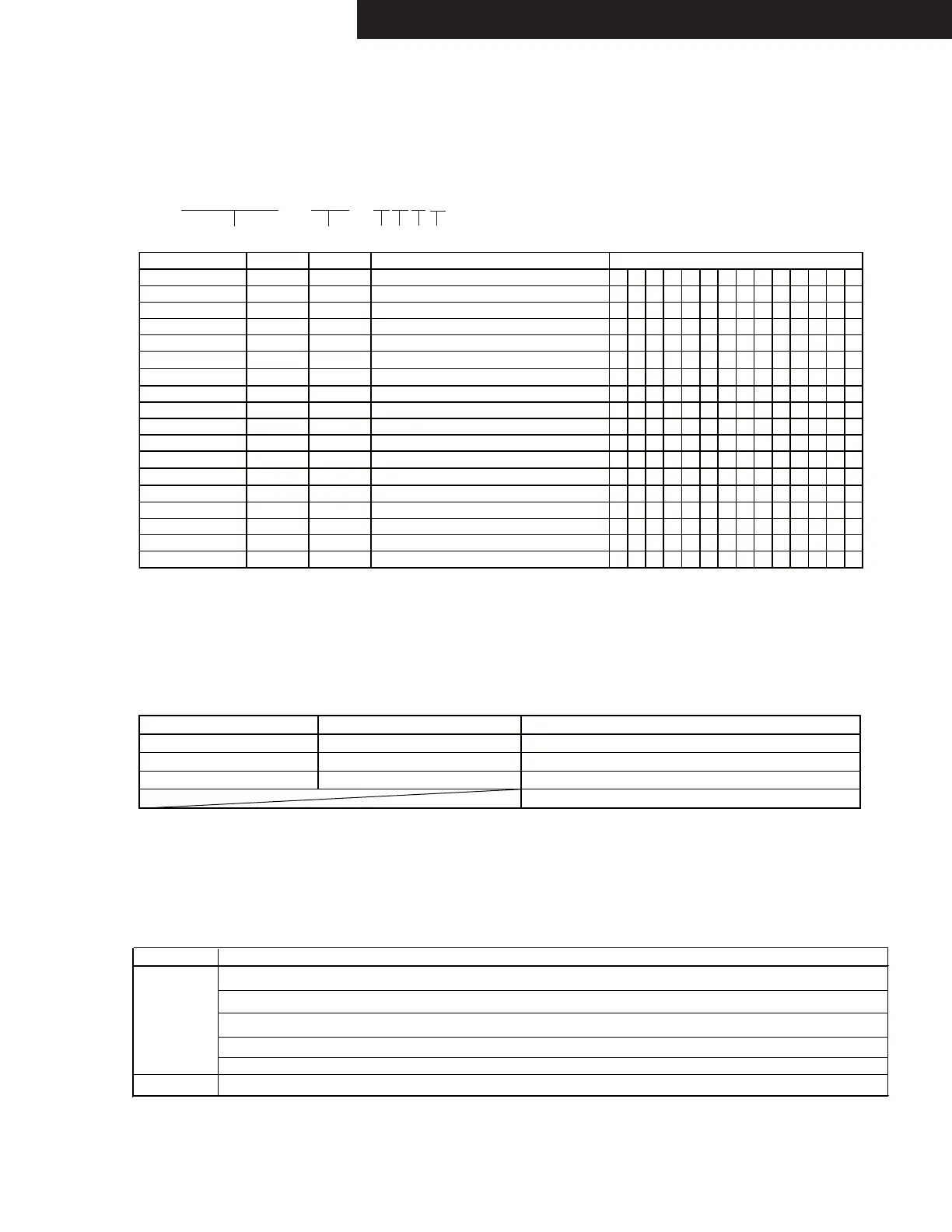
Model Name Distination Number Writing Data
TX-NR1030 Dx 2000 2000 TX-NR1030 Dx
NR1 0 3 0 Dx 2 0 0 0
TX-NR1030 xx 8000 8000 TX-NR1030 xx
NR1 0 3 0 x x 8 0 0 0
TX-NR1030 JJ 4000 4000 TX-NR1030 JJ
NR1 0 3 0 J J 4 0 0 0
DTR-60.6 Dx 2060 2060 DTR-60.6 Dx
DTR606 Dx 2060
DTR-60.6 xx 8060 8060 DTR-60.6 xx
DTR606 x x 80 60
DTR-60.6 JJ 4060 4060 DTR-60.6 JJ
DTR606 J J 40 60
TX-NR3030 Dx 2200 2200 TX-NR3030 Dx
NR3 0 3 0 Dx 2 2 0 0
TX-NR3030 xx 8200 8200 TX-NR3030 xx
NR3 0 3 0 x x 8 2 0 0
TX-NR3030 JJ 4200 4200 TX-NR3030 JJ
NR3 0 3 0 J J 4 2 0 0
DTR-70.6 Dx 2260 2260 DTR-70.6 Dx
DTR706 Dx 2260
DTR-70.6 xx 8260 8260 DTR-70.6 xx
DTR706 x x 82 60
PR-SC5530 Dx 2400 2400 PR-SC5530 Dx
SC5 530 Dx 240 0
PR-SC5530 xx 8400 8400 PR-SC5530 xx
SC5 530 x x 84 0 0
DHC-80.6 Dx 2460 2460 DHC-80.6 Dx
DHC8 0 6 Dx 2 4 6 0
DHC-80.6 xx 8460 8460 DHC-80.6 xx
DHC8 0 6 x x 8 4 6 0
DHC-80.6 JJ 4460 4460 DHC-80.6 JJ
DHC8 0 6 J J 4 4 6 0
1. Set the following VOL level.
3. Press the following button, while "TEST - " is displayed, then each test mode is set.
TEST MODE FOR OPERATION
Do the following operation.
2. [TV/CD] + [ON/STANDBY]
TEST-_
1-00
2-00
3-00
4-00
5-00
6-00
[BD/DVD]
[CBL/SAT]
[STB/DVR]
[GAME]
[PC]
[AUX]
KEY TEST
[MEMORY]
IDLING TIMER / Wi-Fi check
[TUNING MODE]
FL TEST
[DIMMER](RT/PTY/TP)
[ENTER]
FIRMWARE COMBINATION CHECK
Button ButtonTest Mode Test Mode
In the test mode, (TONE)+ button is TEST MODE UP and (TONE)- button is TEST MODE DOWN.
TEST 1-00 → TEST 1-01 → TEST 1-02 - - - - TEST 2-00
e.g.
Model name and destination can be confirmed the following operation.
[TV/CD] + [ON/STANDBY] → [DIMMER](RT/PTY/TP) → [TONE+] *4
CONFIRMATION OF MODEL NAME AND DESTINATION
N R 1 0 3 0 D x 2 0 0 0
FL DIS Name Destination A B C D
A:Value of AD port of BAND
B:Value of AD port of INIT1
C:Value of AD port of INIT2
D:Value of AD port of INIT3
e.g.
IDLING TIMER (TEST 1-01)
This mode is used for aging for idling.
Once the following test mode is set, idling timer mode works.
Idling timer mode includes the following functions.
Test mode TEST 1-01
Function
Timer
Voltage-detection protector check
F/W update route test
Wi-Fi connection check
Z2 DAC route check by playing USB flash device
WAV file L+Rch and Rch repetition (1sec each)
Once the above test mode is set, AVR's status changes to idling timer mode and voltage-detection protector check automatically begins.
If voltage-detection protector check is all OK, Wi-Fi connection check automatically begins.
Even if one channel of voltage-detection protector check is NG, Wi-Fi connection check doesn't begin.
Refer to CONFIRMATION OF VOLTAGE-DETECTION PROTECTORS (next page).
Refer to CONFIRMATION OF UPDATE ROUTE (next page).
Refer to CONFIRMATION OF Wi-Fi CONNECTION (next page).
Refer to CONFIRMATION OF ZONE2 DAC ROUTE (next page).
VOL level : 30
Button Test Mode
<NOTE> Store only one file (the above mentioned) into the USB flash device to avoid making trouble.
 Loading...