TX-NR1030/3030/ PR-SC5530/ DTR-60.6/70.6/ DHC-80.6
OPERATION CHECK-3
1N/A
2VIDEO - OSD
3 DA830 - KG2H
4VIDEO - HDCP TX
5VIDEO - HDCP RX
CONFIRMATION OF VOLTAGE-DETECTION PROTECTORS.(The following model only)
to the following test mode.
2. AVR automatically tests in the following test sequence. And if it is all OK, Wi-Fi test will begin.
3. If FL tube displays Wi-Fi check mode then voltage-detection protectors test will be completed.
TEST 1-01
Test sequence
<NOTE>
Don't connect load nor short speaker terminals.
1-2. [TV/CD] + [ON/STANDBY] → [BD/DVD]
1-1. set the volume level to 30
1. Do the following operation.
1-3. [TONE +]
CONFIRMATION OF UPDATE ROUTE.
2. Once the above mentioned test mode is entered, voltage-detection protectors function is checked automatically first, then update
route check will begin.
If the result of update route check is no problem then Wi-Fi check will begin. If the result is NG then NG message will be shown on
the FL tube.
3. If FL tube displays Wi-Fi check mode then voltage-detection protectors test and update route check are passed.
to the following test mode.
TEST 1-01
1-2. [TV/CD] + [ON/STANDBY] → [BD/DVD]
1-1. set the volume level to 30
1. Do the following operation.
1-3. [TONE +]
CONFIRMATION OF Wi-Fi CONNECTION (The following model only)
1. Setting Wi-Fi routers.
3. Once the above mentioned test mode is entered, voltage-detection protectors function is checked automatically first, then update
route check will begin and then Wi-Fi check will begin.
In Wi-Fi check mode, it connects an access point automatically. Wi-Fi LED flashes during connection.
4. If connection is completed and IP address is successfully acquired, Wi-Fi LED turning lights off and the value of RSSI to an access
point is displayed in dBm.
If the connection is failed, NG is displayed.
In case value of RSSI level isn't showed on the FL tube at all past 4 minutes in this timer mode, judge as NG.
If the connection is failed, exit the idling timer mode by pressing the TV/CD button and please try again from step-1.
TEST 1-01
2. set the following test mode.
02 -55d 01’ 14’’
RSSI(dbm)SSID No Time Counter
e.g.
CONFIRMATION OF ZONE2 DAC ROUTE
1. Connect USB memory or USB storage to AVR front USB port.
3. After being displayed Wi-Fi RSSI level, it will play back wave file from USB storage.
(DTR60.6/DTR-70.6/DHC80.6) After update route check, it will play back wave file from USB storage.)
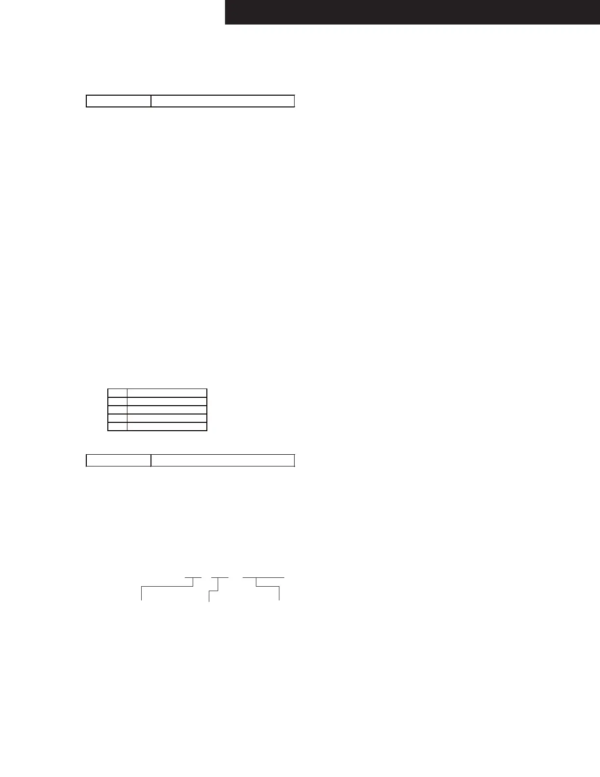
4. Check the wave form that appears L+R and R alternately from the following output terminal.
Output terminal :
ZONE2 PRE/LINE OUT
2. set the following test mode.
TEST 1-01
Detail of NG number of F/W update route test is as below.
Applied model TX-NR1030/3030, DTR-60.6/70.6
(FL+)→(FR-)→(C+)→(SL-)→(SR+)→(SBL-)→(SBR+)→(FWL-)→(FWR+)→(FHL-)→(FHR+)
Applied model TX-NR1030/3030,PR-SC5530
 Loading...