EasyManua.ls Logo

Onkyo TX-SR602 Service Manual

Onkyo TX-SR602
119 pages
To Next Page IconTo Next Page
Page #1 background imageLoading...
Page #1 background image
RC-590M or
RC-591M
TX-SR602
TX-SR602/E
SERVICE MANUAL
SERVICE MANUAL
Ref. No. 3825
092004
120V AC, 60Hz
230-240V AC, 50Hz
120/220-230V AC, 50/60Hz
220-230V AC, 50Hz
AV RECEIVER
MODEL
TX-SR602/E/8260
Black, Golden and Silver models
BMDD,BMDC,SMDC
BMPP,SMPP,BMPA,SMPA,GMPT
BMWT,GMWT
GMGK,GMGQ,GMGR
SAFETY-RELATED COMPONENT
WARNING!!
THE MARK FOUND ON SOME COMPONENT
PARTS INDICATES THE CRITICAL FOR RISK OF
FIRE AND ELECTRIC SHOCK.
WHEN REPLACING, BE SURE TO USE PARTS OF
IDENTICAL DESIGNATION.
MAKE LEAKAGE-CURRENT OR RESISTANCE
MEASUREMENTS TO DETERMINE THAT EXPOSED
PARTS ARE ACCEPTABLY INSULATED FROM THE
SUPPLY CIRCUIT BEFORE RETURNING THE
APPLIANCE TO THE CUSTOMER.

Other manuals for Onkyo TX-SR602

Question and Answer IconNeed help?

Do you have a question about the Onkyo TX-SR602 and is the answer not in the manual?

Onkyo TX-SR602 Specifications

General IconGeneral
Audio Channels7.1
Total Harmonic Distortion (THD)0.08%
Frequency Response10 Hz - 100 kHz
Input Sensitivity200 mV
Signal To Noise Ratio100 dB
Power Output (per channel)90W (8 ohms, 20Hz-20kHz, 0.08% THD)
Input/Output ConnectionsComposite Video, Component Video, Digital Coaxial, Digital Optical, S-Video
Surround Sound FormatsDolby Digital, DTS
Dimensions (W x H x D)435 x 171 x 377 mm
Video InputsComposite, S-Video, Component
Video OutputsComposite, S-Video, Component
Audio InputsOptical, Coaxial

Summary

Specifications Overview

Amplifier Section Specifications

Technical specifications for amplifier power output, distortion, damping factor, and audio response.

General Specifications

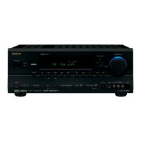
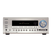
General specifications including power supply, consumption, dimensions, and weight of the unit.

Service Procedures

Replacing the Fuses

Instructions for replacing fuses, emphasizing using identical parts for fire and electric shock prevention.

Safety-Check (USA Models)

Essential safety checks, including leakage current, required after service for USA models.

Setting Voltage Selector

Instructions for setting the voltage selector to match the local power supply for worldwide models.

Schematic Diagram 1: Preamplifier Section (Part 1)

Schematic Diagram 1: Preamplifier Section (Part 2)

Schematic Diagram 2: DSP Section (Part 1)

Schematic Diagram 2: DSP Section (Part 2)

Schematic Diagram 3: Driver Section (Part 1)

Schematic Diagram 3: Driver Section (Part 2)

Schematic Diagram 4: Power Amplifier Section (Part 1)

Schematic Diagram 4: Power Amplifier Section (Part 2)

Schematic Diagram 5: Power Amplifier & Speaker Terminals (Part 1)

Schematic Diagram 5: Power Amplifier & Speaker Terminals (Part 2)

Schematic Diagram 6: Power Supply Section (Part 1)

Schematic Diagram 6: Power Supply Section (Part 2)

Schematic Diagram 9: Microprocessor Section (Part 1)

Schematic Diagram 9: Microprocessor Section (Part 2)

Printed Circuit Board View 1: DSP and Preamplifier (Part 1)

Printed Circuit Board View 1: DSP and Preamplifier (Part 2)

Printed Circuit Board View 2: Driver Circuit PC Board

Printed Circuit Board View 3: Power Amplifier PC Board (Part 1)

Printed Circuit Board View 3: Power Amplifier PC Board (Part 2)

Printed Circuit Board View 4: Speaker Terminal PC Board

Power Amplifier PC Board (NAAF-8391)

Soldering side view of the NAAF-8391 power amplifier PC board.

Printed Circuit Board View 7: Video Circuit Board (Non-European/Australian) (Part 1)

Printed Circuit Board View 7: Video Circuit Board (Non-European/Australian) (Part 2)

Printed Circuit Board View 8: Video Circuit Board (Non-European/Australian) (Part 1)

Printed Circuit Board View 8: Video Circuit Board (Non-European/Australian) (Part 2)

IC Block Diagrams: ADV7172 Video Encoder

IC Block Diagrams: ADV7183A Video Decoder

IC Block Diagrams: CS42518 Codec & CS5333 A/D Converter

IC Block Diagrams: CS494003 Audio Decoder DSP

IC Block Diagrams: LC74763-9836 OSD Controller

IC Block Diagrams: MX29LV040 Flash Memory

IC Block Diagrams: NJW1157 Volume Control IC (Block Diagram)

Microprocessor Connection Diagram (Part 1)

Microprocessor Connection Diagram (Part 2)

Microprocessor Terminal Descriptions (Part 1)

Microprocessor Terminal Descriptions (Part 2)

Adjustment and Confirmation Procedures

Idling Current Adjustment

Procedure to adjust idling current for front, center, and surround channels.

Confirmation of Protection Circuit

Voltage Detection Check

Procedure to check voltage detection for each speaker channel in test mode.

Current Detection Check

Procedure to check current detection and speaker relay behavior with resistors.

Operation Checks: Voltage Sensor and Thermal Protector

Printed Circuit Board Parts List: DSP and Preamplifier (Part 1)

Printed Circuit Board Parts List: DSP and Preamplifier (Part 2)

Printed Circuit Board Parts List: DSP and Preamplifier (Part 3)

Printed Circuit Board Parts List: DSP and Preamplifier (Part 4)

Printed Circuit Board Parts List: DSP and Preamplifier (Part 5)

Printed Circuit Board Parts List: DSP and Preamplifier (Part 6)

Printed Circuit Board Parts List: DSP and Preamplifier (Part 7)

Printed Circuit Board Parts List: DSP and Preamplifier (Part 8)

Printed Circuit Board Parts List: DSP and Preamplifier (Part 9)

Printed Circuit Board Parts List: Power Amplifier PC Board (NAAF-8391) (Part 1)

Printed Circuit Board Parts List: Power Amplifier PC Board (NAAF-8391) (Part 2)

Printed Circuit Board Parts List: Power Amplifier PC Board (NAAF-8391) (Part 3)

Printed Circuit Board Parts List: Power Amplifier PC Board (NAAF-8397) (Part 1)

Printed Circuit Board Parts List: Power Amplifier PC Board (NAAF-8397) (Part 2)

Printed Circuit Board Parts List: Power Amplifier PC Board (NAAF-8397) (Part 3)

Troubleshooting: No Audio in CD/HDCD Hybrids

Service Bulletin: No Sound in Surround Mode

Technical Tip: Unit Locks Up During Auto Speaker Setup

Related product manuals