12 OPAL-RT Technologies OP5700 User Manual
Hardware Interface
Front Connectors
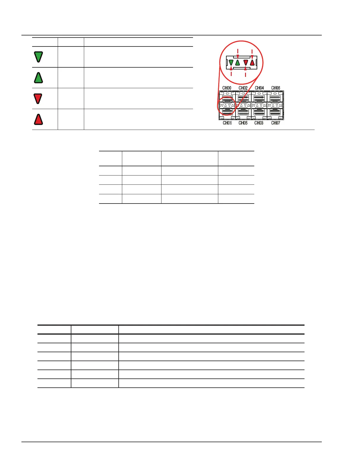
LED Color Description
CH01
CH00
Green ON = SFP transceiver is inserted
OFF = no SFP transceiver is present
BLINK = channel active
Green ON = SFP transceiver is inserted
OFF = no SFP transceiver is present
BLINK = channel active
Red OFF = connection okay
ON = transmission fault
BLINK = reception loss
Red OFF = connection okay
ON = transmission fault
BLINK = reception loss
C. SYNCHRO: synchronization connectors (fiber optic and audio) and a series of four LEDs on the
front panel display the device status
LED Power On After Load & During
Execution
After Reset
Tx OFF GREEN** OFF
Rx OFF GREEN** OFF
M/S Default* ORANGE = Slave GREEN
PWR GREEN GREEN GREEN
Table 2: OP5700 SYNCHRO LEDs
*The color of the LED on power on depends on the default FPGA configuration: when the FPGA
board is programmed in slave synchronization mode, the LED will be orange; when it is programmed
in master mode, the LED will be green.
**Tx and Rx provide synchronization information. When transmitting the synchronization signal, the
Tx LED will be green. When receiving the synchronization signal, the Rx LED will be green.
D. USB connector for JTAG programming (used in the event of lost or damaged FPGA configuration
E. Monitoring RJ45 connectors with mini-BNC terminals for monitoring: RJ45 cables connect from a
channel on an RJ45 panel (A) to one of four RJ45 monitoring connectors (E). Mini-BNC connectors
allow for quick cable connections to monitoring devices (such as an oscilloscope). See “Installation”
for details.
F. Target computer monitoring interface. Two push buttons include POWER in top position to start the
Target computer and RESET in the bottom position to reset the Target computer. There are 6 LED
indicators:
LED NAME Description
Green Power On indicates that the unit is powered up.
Green HDD On indicates that the hard disk drive is operating.
Green NIC1 On indicates that network port 1 is in use.
Green NIC2 On indicates that network port 2 is in use.
Red Power Fail On indicates a power fault.
Red Overheat/Fan Fail On indicates either that unit has overheated or a fan fault.
G. Optional PCI or PCIe connector slots. By default, these spaces will be covered by blank plates if
there are no optional PCI or PCIe boards. If there are boards installed, the spaces will give access
to the card connectors.