OP5700 User Manual OPAL-RT Technologies 11
Hardware Interface
Front Connectors
HARDWARE INTERFACE
FRONT CONNECTORS
A
G
D
CB
E
F
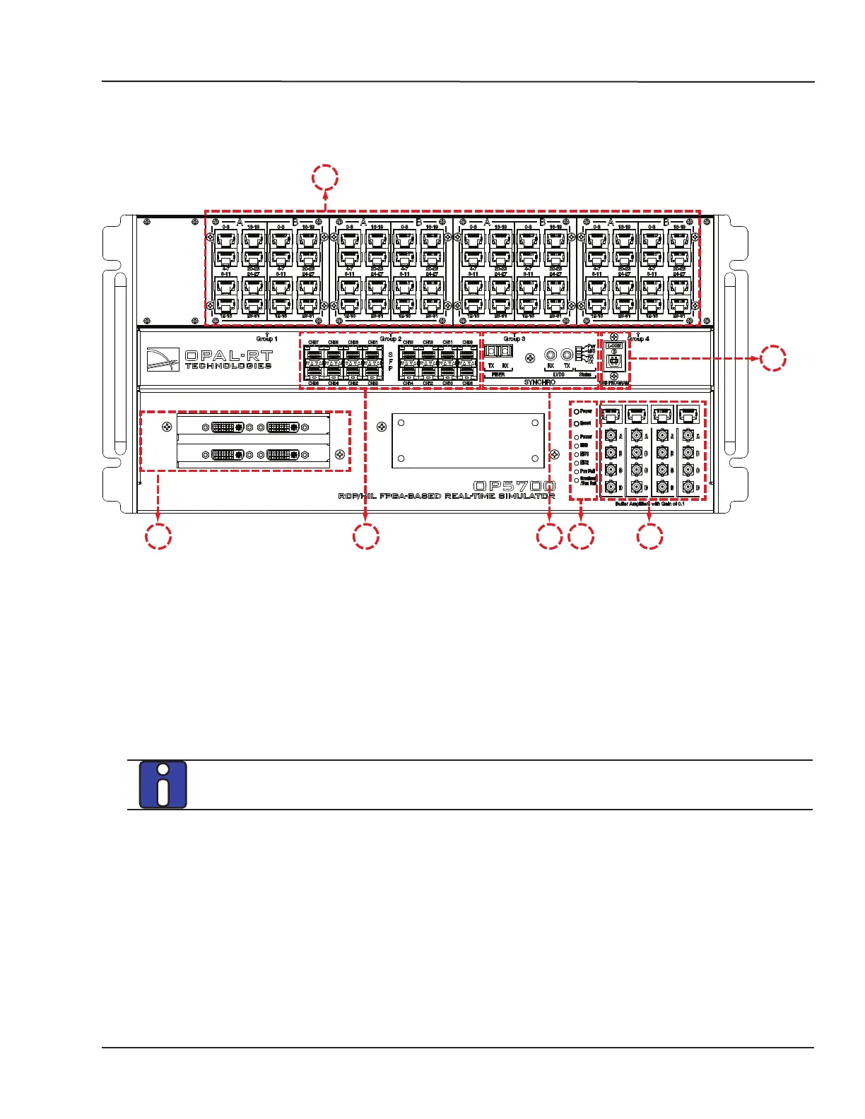
Figure 2: OP5700 front panel
A. RJ45 connector panels provide connections to monitor signals from mezzanine I/O boards.
Each connector is linked to front and back mezzanines on the carrier board. Analog mezzanines
(channels 0-15) will use only the first column of connectors. Digital mezzanines will use both
columns (channels 0-15 in the first column and channels 16-31 on the second column of
connectors). See the “Pin Assignments” for more detailed information.
B. 16 SFP (small form-factor pluggable) ports controlled from the FPGA, for high-speed
communication with other simulator FPGAs or with third-party devices. Each socket controls one
communication link. SFP transceivers and optical fiber cables must be selected according to the
type and speed of the communication protocol implemented in the FPGA.
MUSE link requires specific SFP and cable:
SFP transceiver: Avago AFBR-57R5APZ
Cable: LC-LC multimode 850nm optical fiber
The LEDs (light pipes) associated to the selected channel will light to indicate the channel is
selected. LEDs are arrow-shaped to indicate the channels to which they are associated. The LED
upward arrow points to top channel, the downward arrow points to bottom channel (see below):