18 OPAL-RT Technologies OP5700 User Manual
Installation
Cabling Instructions
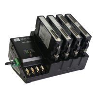
CONNECT THE SCREW TERMINAL
The breakout board provided allows users to access each pin of the DB37 separately through the screw
terminals. Simply insert the breakout board DB37 connector onto the desired DB37 connector on the
simulator.
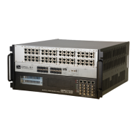
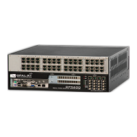
OPAL-RT simulator
DB37 connectors
Screw terminal
Figure 10: Connecting the screw terminal board
Refer to the simulator or board user manual for exact pin assignments
CONNECT THE OPTICAL FIBER CABLE
The optical fiber cable is used to establish synchronization connections between simulators (as shown
below) .
Figure 11: Connecting synchronization cables