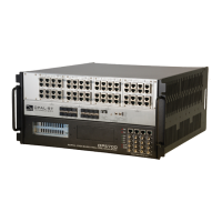
OP5700 User Manual OPAL-RT Technologies 17
Installation
Cabling Instructions
CONNECT THE LOOPBACK KIT
NOTE
The following procedure is only used for test purposes when no external source is available.
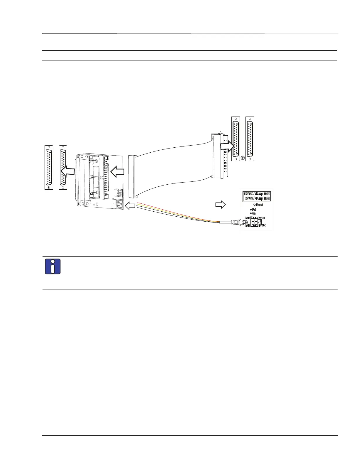
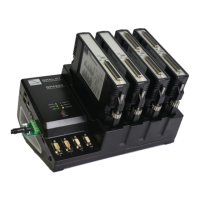
The loopback kit included in the starter kit allows users to test system signals. Connection is made easy
with a custom flat cable that matches OPAL-RT standard DB37 pin assignments.
• Connect one end of the flat cable to the loopback board
• Connect the loopback board to the simulator DB37 Output signal
• Connect the other end (DB37 connector) of the flat cable to the simulator DB37 Input signal
• Connect the VUser (required to preserve isolation) from the loopback board to the OP5700.
SIMULATOR
OUTPUT
LOOPBACK BOARD
SIMULATOR
INPUT
To OP5xxx
series
simulator
OP5700 series simulator
(not isolated)
Figure 9: Connecting the loopback kit
Although some boards do provide a power source, using that would compromise the
isolation. OPAL-RT recommends using external power source: the user must connect the
power wires (provided) to either a 5 or 12 V power source. Make sure that the Vuser source
switch on the loopback board is set to “External”.