20 OPAL-RT Technologies OP5700 User Manual
I/O Configurations
DB37F Connectors
I/O CONFIGURATIONS
The OP5700 simulator provides signal conditioning for up to 256 I/Os, which are managed from the
FPGA module and are accessible via DB37 and RJ45 connectors in the back and front of the chassis.
I/O lines are routed through a carrier board (inside the chassis) that can accept up to 8 signal
conditioning modules, which provides greater signal conditioning flexibility. The conditioning modules
follow a proprietary form factor, called Type B mezzanines. A range of mezzanines are available for
analog and digital conditioning.
Mezzanines are detected at power up and information is processed by th FPGA for verification and
initialization (I/O line direction, analog module calibration coefficients, etc.). Then, mezzanines are
made available to the CPU simulation to detect improper configuration or hardware failure.
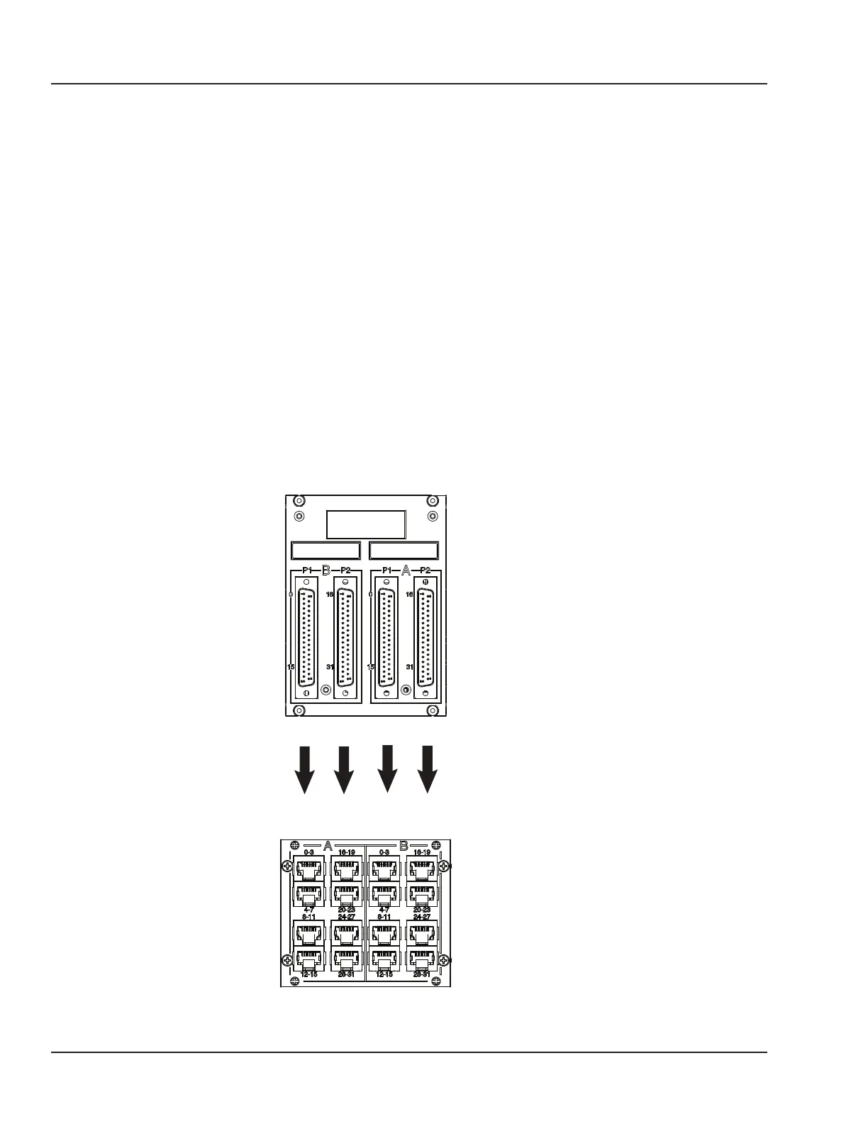
DB37F CONNECTORS
There are 4 groups of mezzanines, labeled 1 to 4; each pair (A & B) is linked to four female DB37
connectors (I/Os) on the back of the chassis:
The first two connectors (left to right) represent channels from Group B, which are linked to the
conditioned channels from the rear mezzanine. The last two connectors (left to right) represent
channels from Group A, which are linked to the conditioned channels from the front mezzanine.
DB37 connector panel
Signal out
from OP5700
to monitoring
(via BNC)
RJ45 Connector Panel
Group 1
GROUP B
Signal in
from device
to OP5700
Figure 13: DB37 connection to analog mezzanines