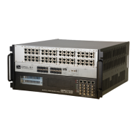
OP5700 User Manual OPAL-RT Technologies 15
Installation
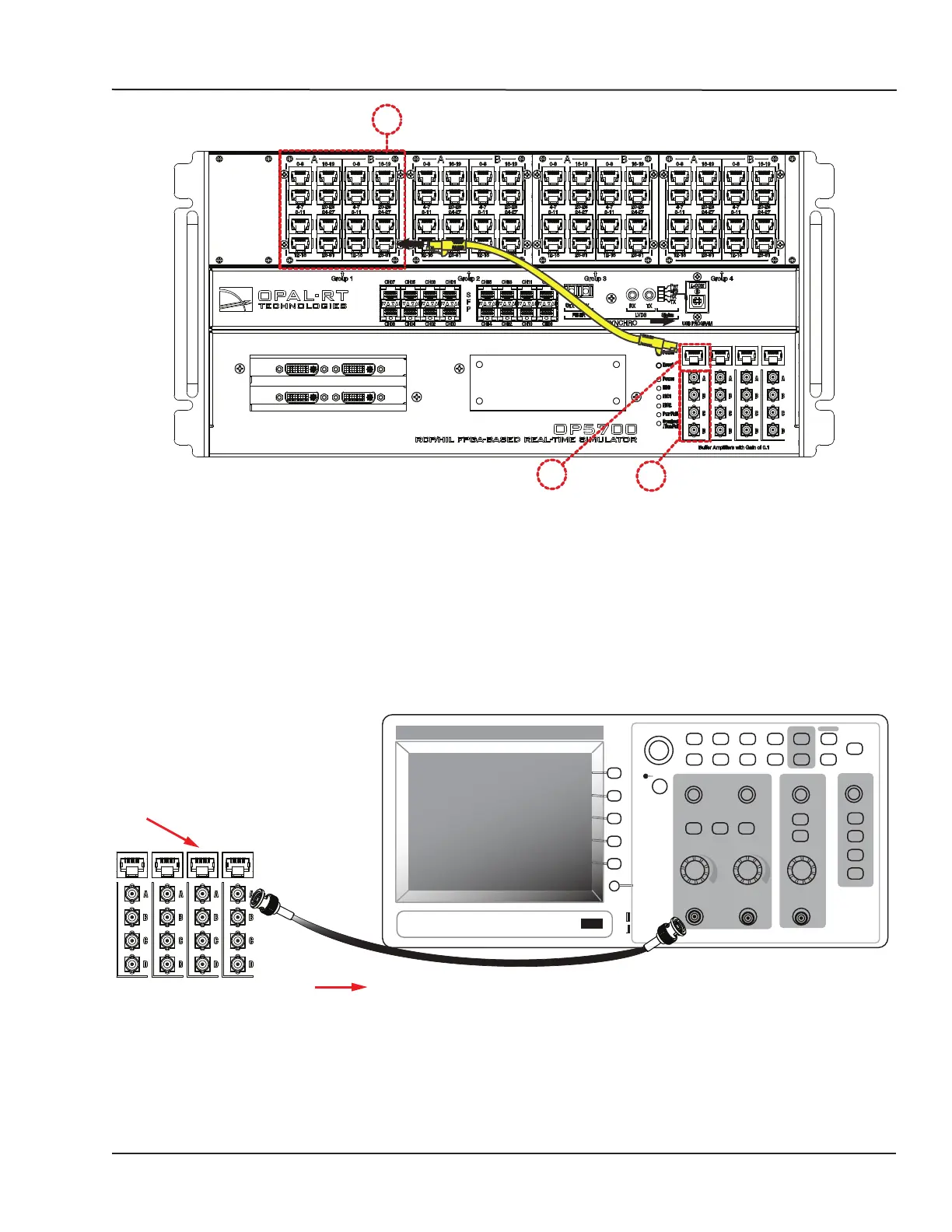
Cabling Instructions
A
B C
Figure 5: How to connect RJ45 cables for monitoring
A. Connect one end of the RJ45 cable to the desired channels (A). See for RJ45 connector pinouts
B. Connect the other end of the RJ45 cable to the monitoring connector (B)
C. Connect BNC cable connectors as shown in Figure 6. These are labeled A, B, C, D and each
connector represents a channel. Using the image as an example, the connectors represent
channels in the following order; A = channel 28, B = channel 29, C = channel 30 D = channel 31.
CONNECT MINI BNC TO BNC
These cables establish connections between OPAL-RT hardware and external monitoring devices.
Individual channel
monitoring
To external
monitoring device
From simulator
channel bank
CH 1
MENU
MATH
MENU
CH 2
MENU
HORIZ
MENU
SET TO
ZERO
TRIG
MENU
SET TO
50%
FORCE
TRIG
TRIG
VIEW
PRINT
REF
MENU
RUN/
STOP
SINGLE
SEQ
AUTORANGE
SAVE/RECALL MEASURE
ACQUIRE
HELP
UTILITY
CURSOR
DISPLAY
DEFAULT SETUP
SAVE
AUTOSET
Figure 6: Connecting BNC monitoring cables
Connect a mini-BNC cable to each jack (C) and connect the other end of the cable to the desired
monitoring device.