Technical data and exploded views
- 15 -
optek-Manual--1004-2003-02--AF45-US-2011-01-04
www.optek.com
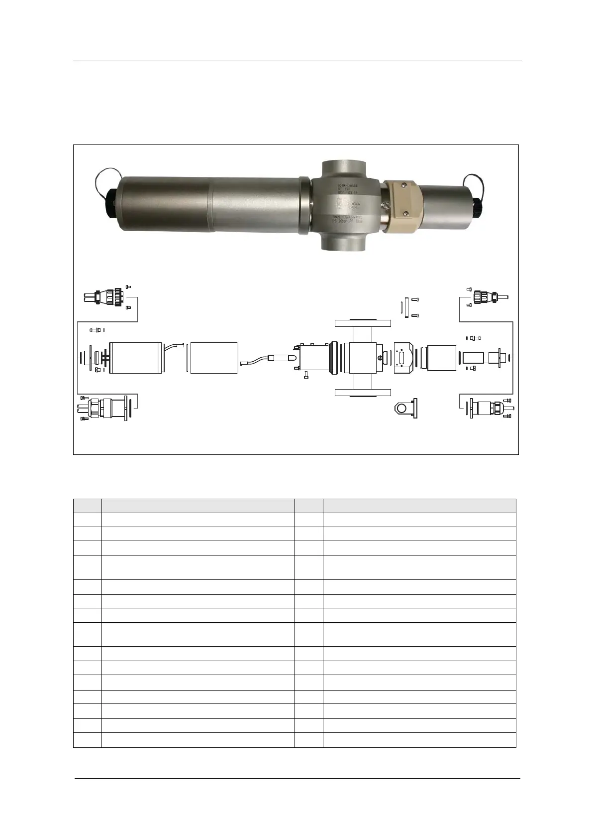
5.7 Exploded view of AF45-VB-PV sensor
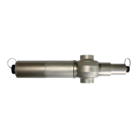
Fig. 9 Photo and exploded view of AF45-VB-PV
23 922
2829
11 1 0 9 8
2830
13 12
37 6 5 19
24
4 3 3 2 14 15
27 18
1716 9 18
11 2625
12
23
20
21
28 30
28 29
1
Tab. 9 Exploded view explanations
No. Explanation No. Explanation
1 Sensor body 16 Detector adapter AF45-HT-VB, PEEK
2 Window ring M58 x 1.5, incl. 8 screws M5 17 Optical housing OH06 Purge, 1.4571 (316Ti)
3
O-Ring 50.52 x 1.78, Viton
®
18
O-Ring 21.95 x 1.78, Viton
®
4
Housing lamp assembly AF45, incl. wavelength mod-
ule (see table 17 on page 38)
19
Detector module AF45, incl. wavelength module (see
table 18 on page 39)
5 Screw M4 x 10 DIN 912 A4 20
O-Ring 10.10 x 1.60, Viton
®
6 Lamp module AF45 21 Detector cable AF45
7 Optical housing OH2 22 Lamp cable AF45 with SS plug protector
8 HVPS (high voltage power supply) for AF45 23
4 screws M3 x 12 (DIN 7985), 1.4571 (316Ti), incl.
washer
9
O-Ring 31.47 x 1.78, Viton
®
24 Detector cable AF45 with SS plug protector
10 Lamp socket 25 Sealing cover FH03
11
O-Ring 18.77 x 1.78, Viton
®
26 2 screws M3 x 10 DIN 7985 A4, incl. washer
12 4 screws M3 x 6 (DIN 7985), 1.4571 (316Ti) 27 Validation filter in FH03
13 Lamp cable AF45 28
O-Ring 4.00 x 1.00 Viton
®
14 Window ring M24 x 1.5, incl. 8 screws M5 29 Screw M5 x 6 (DIN 84), 1.4571 (316 Ti)
15
O-Ring 25.12 x 1.78, Viton
®
30 Purge connection M5, Ms/Ni