Connection to converter C4000
- 20 -
optek-Manual--1004-2003-02--AF45-US-2011-01-04
www.optek.com
7 Connection to converter C4000
For connecting the sensor cables, observe the following basic conditions:
• Bring the sensor cable to the cable entry from underneath.
• Form a loop with the sensor cable close to the cable entry.
• Do not lay sensor cables in ducts of current-carrying lines.
• Observe cable specifications (s. technical data).
• To lay sensor cables underground without protection is prohibited.
Sensor cables are provided to connect the sensor to the converter. The sensor
cable to the lamp consists of at least two lines, one for lamp power supply and
one for the reference detector, for measurement of the lamps' light intensity.
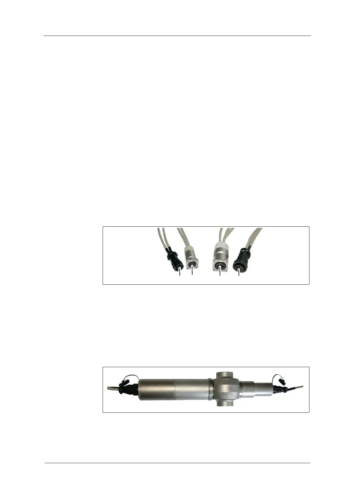
Sensor cables on the sensor side are equipped with plug protector (21, 23;
fig. 14) or do not have plug protector (13, 20).
Connection to the
sensor
On the sensor side, mixing up sensor cables is not possible, as connectors are
distinctive:
• 9-pin connector on the detector side (20, 23),
• 16-pin connector on the lamp side (13, 21)
Fig. 14 Connector with and without plug protector
Tool
• not needed
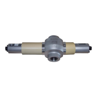
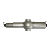
Connection of the sensor cable without plug protector on the detector and lamp
side:
1. Loosen the connection cover of the sensor.
2. Plug in the sensor cable.
3. Screw-tighten the protection cover.
Fig. 15 Connection of the sensor cable without plug protector, example AF45