Installation
- 17 -
optek-sensors AS56, Version 04.2010_1.2US, 15.04.2010
www.optek.com
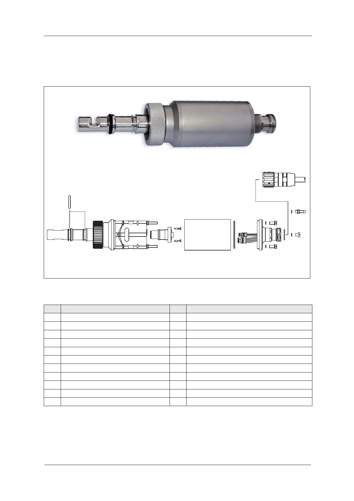
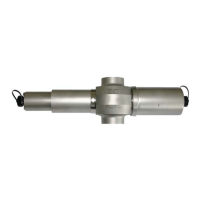
4.8 Exploded view of AS56-F / AS56-N sensor
Fig. 10 Photo and exploded view of AS56-F / AS56-N
121617 15 8 14813 811 10 9 376 54 2
421
18 19
422
20
1
Tab. 8 Exploded view explanations
No. Explanation No. Explanation
1 O-Ring 18.0 x 1.5 NBR 70 12 2 threaded rods M4 x 87 DIN 976 A2
2 Probe socket AS56 13 Connection detector
3 2 cylinder nuts M4, 1.4571 (316Ti) 14 Lamp holder AS56
4
O-Ring 4.00 x 1.00 Viton
®
15
Swivel nut 35 G1
1
/
4
’’ H19
5 Backplate OH 02 16 Probe body AS56 polished
6 Phoenix plug 2-pin (lamp) 17 Measuring segment AS56, variable OPL
7 Phoenix plug 3-pin (detector) 18 Option: O-Ring 18.64 x 3.53, EPDM, lower groove
8
O-Ring 50.52 x 1.78, Viton
®
19 Option: O-Ring 18.64 x 3.53, EPDM, upper groove
9 Housing OH02 20 Probe cable AS56
10 2 captive screws M2.5 x 10.8 (slot) 21 Screw M5 x 6 DIN 84 A4
11 Lamp module AS56 22 Purge connection M5, Ms/Ni