The front panel and rear panel
OPTIMUM
MASCHINEN - GERMANY
15 / 06 / 2011Page 14 The front panel and rear panel Digital position display DPA 2000/ DPA 2000S ; Version 2.1.2
© 2011
GB
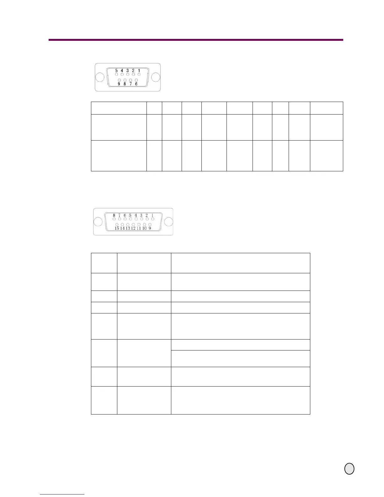
2.6 Input/output connection
The meanings of the prong signal of a 15-pin D-type socket are listed in the following table:
PIN No.
12 3 4 5 67 8 9
sine 1Vpp signal
for OPTIMUM mea-
suring gibs ML
0° 180° +5V 0V 90° 270° Z Blank Shielding
TTL square wave
signal, for
OPTIMUM magnetic
measuring system
A+ A- +5V 0V B+ B- Z+ Z- Shielding
PIN
No.
Meaning Destination
1
Photoelectric switch
Plus
Tachometer photoelectric switch pulse output
2 +12V Tachometer photoelectric switch power supply Plus
3 Initial signal SIN External switch initial signal
5
Speed adjustment
output
ADJ
Transducer frequency setting terminal
6
Digital grounding
DGND
Tachometer photoelectric switch power supply Minus
External switch common cable
7
Low speed state
LIN
External switch low speed signal
9
Analog grounding
AGND Transducer analog signal common terminal