OPTIMUM
MASCHINEN - GERMANY
Description of the basic operation
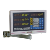
15 / 06 / 2011 Page 31Description of the basic operation Digital position display DPA 2000/ DPA 2000S ; Version 2.1.2
© 2011
GB
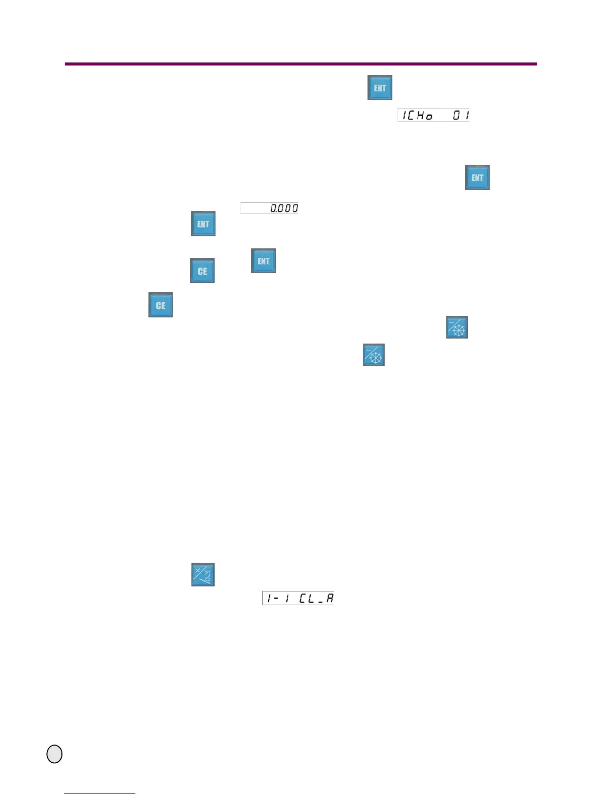
Enter the value of the end point angle and press the key to confirm the value.
After completing the entry of the parameters, it will switch to the function automatic
machining. The display screen on the upper right will show indicating that
the sequence number of the hole being machining currently is 01.
The two axes related to the selected coordinate layer will display the coordinate values rela-
tive to the position of the hole being machined currently. The other axis will be displayed nor-
mally.
II.While in the dividing hole on the circle machining state, after pressing the key to
select the number of the hole, you may move the machine tool until the
X and Y axes display . This is the position of the hole on the circle.
Press the key to select the next hole and the sequence number of the hole ascends.
When the entered sequence number of the hole is the same as the entered number of the
divided holes, press the key to return to the No. 01 hole.
Press the key to return to the position of the preceding hole and the sequence number
of the hole descends. When the entered number of the hole switches over to 01, press the
key again to return to the position of the last hole.
III. After completing the dividing hole on the circle machining, press the key to return to
the standard display.
If it is in the dividing hole on the circle state, press the
key to interrupt the function and to return to the standard display except for the cases mentioned
above.
4.14 Machining along the oblique line function
Function introduction: To perform the inclined line machining operation on the selected
coordinate layer and can be used in machining inclined slots or inclined layers.
A description to the parameter needs to be defined:
- Inclined angle of the inclined line (CL-A): The inclination between the inclined line
segment to be machined and the X-axis along the positive direction (on the YZ layer an
inclination between the layer and the Y-axis along the positive direction).
Operation procedures:
I. Parameter entry:
Move the cutter of the machine tool to align the first point of the inclined line to be machined,
press the key and enter machining function for the inclined line. The display screen
on the upper right appears indicating that the angle of the inclined line can
now be entered.
The X-Y coordinate layer is the default layer.
The LEDs on the X-axis display the last value of the angle of the inclined line. The last ente-
red value will be displayed on the LEDs on the Y-axis.