Description of the basic operation
OPTIMUM
MASCHINEN - GERMANY
15 / 06 / 2011Page 28 Description of the basic operation Digital position display DPA 2000/ DPA 2000S ; Version 2.1.2
© 2011
GB
Operation procedures:
I. Parameter input:
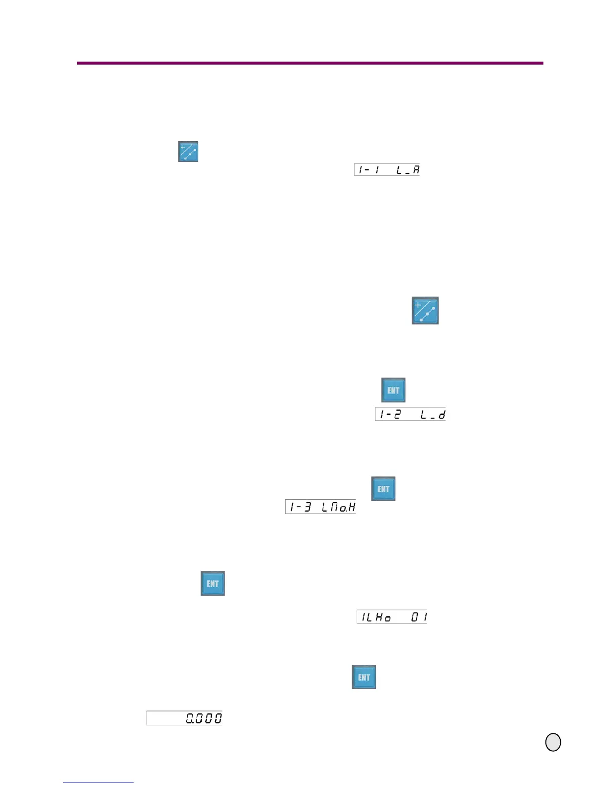
Move the cutter of the machine tool to align the first point of the hole of the oblique line, press
the key and enter the dividing hole along an oblique line function.
The display screen on the upper right appears indicating that the angle of
the oblique line can now be entered. The furthest "1" to the left indicates the selected default
XY-coordinate layer .
The LEDs on the X-axis display the last value of the angle of the oblique line. The last ente-
red value will be displayed on the LEDs for the Y-axis.
Note: While performing the functions of dividing hole along the oblique line, dividing hole on the
circle, machining along oblique line and the arc machining, the display screen on the upper right
always shows the selected coordinate plane by the furthest digit on the left:
1---the XY-plane, 2-the YZ-plane, 3-the XZ-plane.
We only take the XY-layer as an example to explain the operation procedures.
If you want to change the coordinate plane, just press the key several times, the
coordinate plane will change according to the following sequences:
- To change from the XY coordinate to the YZ coordinate layer;
- To change from the YZ coordinate plane to the XZ corrdinate layer;
- After exiting the dividing hole along the oblique line function, the digital display returns to
the standard display.
Enter the angle of the oblique line and then press the key to confirm your entry
The display screen on the upper right will change to indicating that you
can now enter the length on the oblique line.
The LEDs on the X-axis will display the previous value of length of the oblique line, and the
last entered value will be shown on the LEDs for the Y-axis.
Enter the length of the oblique line, and then press the key to confirm. The display screen
on the upper right will change to indicating that you can enter the number of
holes to be divided on the oblique line.
The LEDs on the X-axis will display the last value of the number of holes divided on the oblique
line, and the last entered value will be displayed on the LEDs for the Y-axis.
Enter the number of holes to be divided on the oblique line, and
press the key to confirm.
After having input all parameters, enter the status for automatic machining.
The display screen on the upper right will show indicating that the
sequence number of the hole being currently machining is 01.
The two axes related to the selected coordinate layer will display the coordinate values rela-
tive to the position of the hole being currently machined. The other axis will display normally.
II. During the machining status, after pressing the key in order to select the number of the
hole,
you may move the machine tool until the two axes of the selected layer are all displayed
. And this is the position of the corresponding hole.