
R
Robert Dunn DDSAug 5, 2025
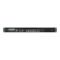
What to do if I cannot access the Talari APNA Web Console on Oracle Talari E100?
- JJennifer SnyderAug 5, 2025
If you cannot access the Talari APNA Web Console, first, ensure you are using the correct IP address. Second, confirm that the management port of the E50 APNA is connected to a switch and that there is network activity.