ST 6100 - HARDWARE GUIDE
LIST OF FIGURES
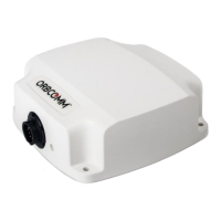
Figure 1: ST 6100 9
Figure 2: ST 6100 with Side Connector 10
Figure 3: ST 6100 with Bottom Connector 10
Figure 4: Terminal Connector Pin Assignment (Male) 14
Figure 5: View of terminal Male Connector 15
Figure 6: Face View of Mating Connector (Female) 15
Figure 7: Rear View of Mating Connector (Solder Cups) 15
Figure 8: Digital Input 19
Figure 9: Digital Output 20
Figure 10: Analog Input 21
Figure 11: Analog Accuracy by Limiting Voltage Drop on Return Current 22
Figure 12: Analog Accuracy with Independent Analog Reference 22
Figure 13: Accelerometer Axis 25
Figure 14: ST 6100 Top View Side Connector Enclosure Dimensions 26
Figure 15: ST 6100 Side View Enclosure Dimensions 27
Figure 16: ST 6100 Top View of Bottom Connector Enclosure 27
Figure 17: ST 6100 Bottom View of Bottom Connector Enclosure 28
Figure 18: ST 6100 Side View of Bottom Connector Enclosure 28
T406, VERSION 01
6
© ORBCOMM PROPRIETARY