TECHNICAL MANUAL BLUE PAPER ORDU · OMX 202146 | ORBEA ORBEA | 47
EN
4
6 N.m
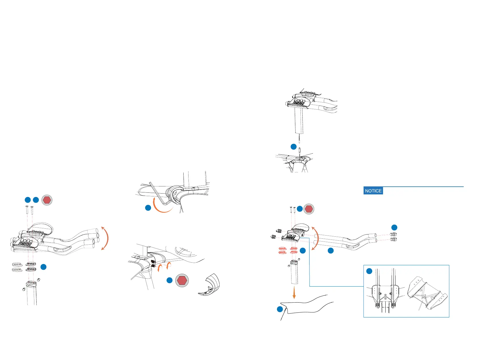
BRIDGE AND EXTENSIONS
ANGLE ADJUSTMENT
Ordu allows the bridge and extensions angle to be adjusted within a 15º range by using angle
setting wedges between the front post and the bridge. To install or remove wedges, follow the
method below:
3
To install or remove wedges on mechanical assemblies
(no Di2 or Etap), it is not necessary to remove the front
post from the bicycle or the extensions from the bridge:
7UGCOO#NNGPMG[VQTGOQXGVJGDTKFIGƂZKPIDQNVU
to the front seat post.
2. Remove or install the necessary angle setting wedges
to achieve the desired angle. Do not install more than
3 wedges.
3. Re-install the bridge onto the front post and tighten the
bolts to the recommended toque setting.
To modify the bridge angle by removing or installing angle
setting wedges and assemblies with electronic gears, it is
necessary to remove the bridge-axtensions assembly from
the bicycle and disassemble all the elements to extract the
electronic gears cable to the extensions switches, which
will allow wedges to be added or removed.
1. Use an Allen key on the hole on the bottom of the han-
dlebar front cover as a lever to unclip it from the base
handlebar.
2. Use an 3mm Allen key to loosen the front post clamp.
MECHANICAL GEARS ASSEMBLIES ELECTRONIC GEARS ASSEMBLIES
Allen 3 mm.
1
3
4 N.m
2
3. Remove the front post-extensions assembly from the
bicycle and disconnect the extensions Di2 cable.
4. Remove the electronic switches from the extensions
and disconnect them from their cable.
9KVJCOO#NNGPMG[TGOQXGVJGDTKFIGƂZKPIDQNVU
to the front post.
6. Loosen the bridge extensions clamps and remove the
extensions form the bridge.
7. Carefully remove the Di2 cable from the bridge and
the front post through the bottom of the front post.
8. Install or remove the necessary angle setting wedges
to achieve the desired angle. Do not install more than
3 wedges.
9. Re-install the Di2 cable through the front post, the
wedges, the bridge and the extensions.
10. Re-assemble all components following the recom-
mended torque settings.
5
8 6
4
7
10
Read the Cable routing section of this ma-
nual for a more detailed description of the
Di2 cable routing through the bridge.
2
4
1 3
4
6 N.m
15º
15º
 Loading...