Operating by front panel
−
17
−
6 Operatingbyfrontpanel
This section explains how to operate the product with ease at the factory setting when receiving the product.
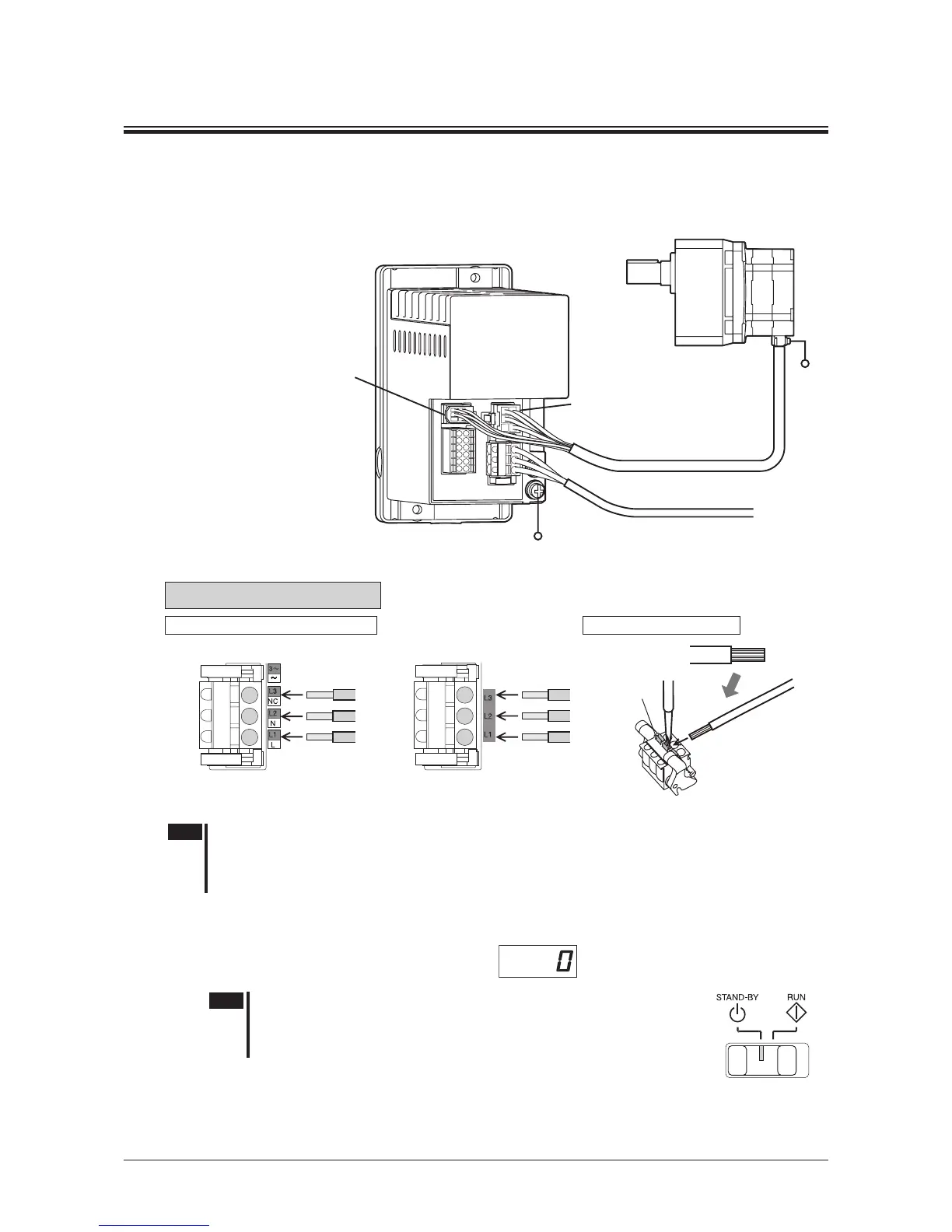
6.1 Connecting
Motor connector of the motor: White
䊻Connect the connector to the CN2
Sensor connector of the motor: Black
䊻Connect the connector to the CN3
PE
PE
Power supply
Connect the connector
to the CN1
Connecting the power supply
Example: Three-phase 200-240 V
Strip the insulation
cover of the lead wire
Insert the lead wire
while pushing the
button of the orange
color with a screwdriver.
Button of the
orange color
Connecting to the CN1
Connect the AC power supply to the CN1 according to the input voltage.
•
200 W type
•
400 W type
Note
•
When cycling the power or plugging/unplugging the connector, turn off the power and wait for 1 minute
or more before doing so.
•
Ensure that the connector plugged in securely. Insecure connections may cause malfunction or damage
to the product.
6.2 Inputtingthepower
Turn on the power after connecting as
shown in the gure above.
Indication: Rotation speed
Note
When inputting the power, if the operation switch is set to the RUN side, the
alarm code "
AL46
" (prevention of operation at power-on) is displayed, and
the operation cannot be executed.
Set the operation switch to the STAND-BY side and turn on the power.
Operation switch
*
Refer to p.33 for "prevention of operation at power-on" (alarm code: AL46).
Refer to the next page "6.3 Operating" for how to operate.
Refer to p.12 for the connecting the power supply.
 Loading...