15
WELD INDICATORS
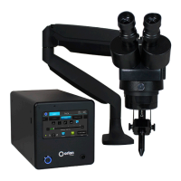
Power on the Orion 250i2. Once powered on, there are two indicator dots in the top left corner of the
screen. e top dot indicates the Weld Ready signal. e bottom dot indicates the Weld Good signal.
a. e Weld Ready dot will be red if the welder is not ready to weld, or green if the welder is ready to make
a weld.
b. e Weld Good dot will be red if the most recent weld was bad, green if the most recent weld was good,
or gray if a weld has yet been performed.
IGNITION SCREEN
Clicking on the “Ignition” button navigates to the screen pictured below where the user can adjust various
aspects of the weld discharge timing.
1. “LIFTOFF DELAY” controls the time between tip retraction and weld. Lower values will produce better
arc ignition consistency, but will contaminate the electrode tip more easily - resulting in shorter tip life.
Higher values will increase tip life, but will decrease the arc ignition consistency.
•If the EV unit seems to be misfiring often, clean and re-sharpen the tip of the electrode. If the problem
persists, try lowering the Lift-off Delay value. Make adjustments in increments of 10-20uS at a time,
because this delay can make a big difference.
•If the electrode seems to be sticking to the workpiece surface a lot, or the electrode tip seems unusually
contaminated, raise the Lift-off Delay value. Again, it is best to only adjust by 10-20uS at a time.
2. “MINIMUM TIME BETWEEN WELDS” controls the minimum amount of time that must transpire before
another weld can occur.
3. “TIP RETRACT DISTANCE” controls how far off the surface the electrode tip will be when a weld occurs.
Lower values will produce better arc ignition consistency.
4. “Head Travel Delay” controls how long it takes for the head of the nozzle cone to reach the welding
surface.
THE “STANDARD +” mode is recommended for most EV applications, but experimentation may show that
the other modes are better suited for specific applications.
 Loading...