Do you have a question about the Orion 250i2 EV CNC and is the answer not in the manual?
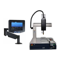
Describes mounting the welder beside the CNC table using an articulating arm.
Details mounting the welder to the side bracket of the CNC table.
Instructions on how to clean and shape the welding electrode using a dremel.
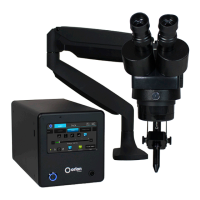
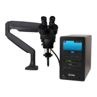
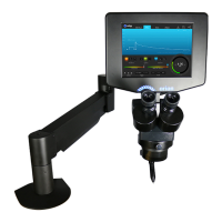
Overview of the welder's main control screen and its interface elements.
Explains the circular dial for adjusting weld energy or power output.
Details different waveform selections and their effect on energy release.
Describes ignition options controlling electrode tip position at energy release.
Explains the high-frequency agitation feature to improve weld formation and strength.
Describes how weld length adjusts the duration of energy discharge.
Explains how chosen parameters affect the weld discharge shape visualization.
Details functions for controlling welds and resetting parameters.
Instructions on preparing the EV screen for welding by pressing 'Play'.
Explains the indicator dots for weld ready and weld good signals.
Details the screen for adjusting weld discharge timing aspects.
Connects the hand-held control unit/pendant to the CNC table.
Powers on the CNC table and the Orion 250i2 welder.
Initializes the robot by pressing the 'F4' button on the pendant.
Ensures the pendant is set to 'Teaching Mode' for operation.
Guides setting welding parameters like waveform, ignition, and power.
Adjusts advanced ignition settings like lift-off delay and retract distance.
Secures the fixture to the CNC table using M4 screws.
Selects and creates a sample program using Program 1.
Selects 'JOG' mode to move the robot with arrow buttons.
Moves the weld head to the first weld location and sets coordinates.
Chooses 'Weld Point' as the type for the defined coordinate.
Navigates through created points and creates the next weld point.
Configures program settings like weld timeout and saves progress.
Experiments with PLC inputs and outputs for testing.
Uses I/O test to manually trigger a weld on the welder.
Runs the entire programmed weld sequence for testing.
Connects the Janome to a PC via Ethernet RJ45 cable.
Retrieves the Janome's IP address using the pendant.
Navigates pendant menus to access administration settings.
Accesses Ethernet settings to find the IP address.
Disconnects pendant and connects bypass connector for setup.
Sets welding parameters like waveform, ignition, and power.
Adjusts advanced ignition settings for weld timing.
Sets up the fixture to the table for robot operation.
Installs JR-C-Points software and configures Ethernet settings.
Registers the robot by entering its IP address.
Selects the registered robot and sets it as the target.
Receives calibration and teaching data from the PC to the Janome.
Initiates communication between the PC and the Janome robot.
Confirms successful communication between PC and Janome.
Initializes the robot and moves parameters to the 'Home' position.
Confirms the robot is in its home position after initialization.
Adds a new point to the robot program for welding.
Sets the type of the added point to 'Weld Point'.
Opens the JOG window to control robot movement.
Uses cursor buttons to move the robot head for positioning.
Updates coordinates and moves the weld head to the target location.
Adjusts Z axis to meet force indicator specifications for positioning.
Confirms the position of the first weld point.
Copies X, Y, Z coordinates from the JOG window.
Pastes the copied coordinates into the point window.
Ensures point window coordinates match JOG window values.
Adds another point and moves the weld head to the next location.
Saves the current progress of the robot program.
Accesses individual program settings for customization.
Configures specific weld settings within the program.
Sets weld timeout and error handling actions.
Sets PTP conditions like speed, mode, and Z axis distances.
Saves data and sends it to the Janome robot.
Transmits the complete program data to the robot.
Moves the weld head to a programmed weld point.
Displays external I/O status and allows manual weld triggering.
Steps to power up the Orion 250i2 welder and weld head.
Covers pre-operation checks like electrode, gas, and system readiness.
Instructions for attaching fixtures and placing workpieces.
Guides positioning the weld head using the teach pendant and Z axis.
Recommends starting with Triangle Weld Mode and low power.
Procedures for running the programmed weld sequence.
Advice on keeping the electrode clean and understanding its condition.
Explains how electrode tip geometry affects weld quality.
Describes the process for sharpening electrodes using a grinding wheel.
Importance of keeping the gas cone clean for proper welds.
Discusses how metal properties influence weld success.
Guidance on material thickness and component arrangement for welding.
Information on how different metal alloy combinations affect welds.
Recommends spring force levels for performing welds.
Discusses factors influencing weld behavior and finding correct settings.
Emphasizes reading the manual and following instructions.
Provides generalized safety advice for the welding industry.
Details precautions to prevent fires and explosions during welding.
Outlines critical safety measures to prevent electrical shock.
Recommends essential PPE for flying sparks, arc rays, and welding.
Warns about hazards associated with hot metal and cables.
Discusses health hazards from welding fumes and gases.
Precautions to prevent equipment from falling during operation or storage.
Advises individuals with medical devices to keep away from operations.
Guidelines to prevent equipment overheating during strenuous use.
Lists key safety standards relevant to welding operations.
Specific warnings and cautions for operating the CNC table.
Addresses issues with weld spot appearance and pitting.
Troubleshoots why the gas cone contacts workpiece but no weld occurs.
Solves problems with the welder not detecting the weld head.
Provides solutions for electrodes sticking or leaving metal flags.
Addresses inconsistencies in weld spot size or missed welds.
Discusses the maximum sheet thickness that can be welded.
| Brand | Orion |
|---|---|
| Model | 250i2 EV CNC |
| Category | Welding System |
| Language | English |