23
Step 25:
PLC inputs and outputs
Next we will experiment with the PLC inputs and outputs.
1. If not already set, pick a weld point and press “GO” to move the robot to one of
the already configured weld points.
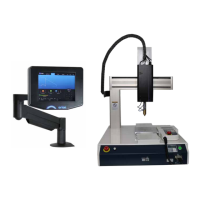
2. Press the “UTILITY” button.
3. Scroll down to “Test Menu” and press the “ENTR” button.
Step 26:
Scroll down to “I/O Test” with the cursor buttons and press the “ENTR” button.
Step 27:
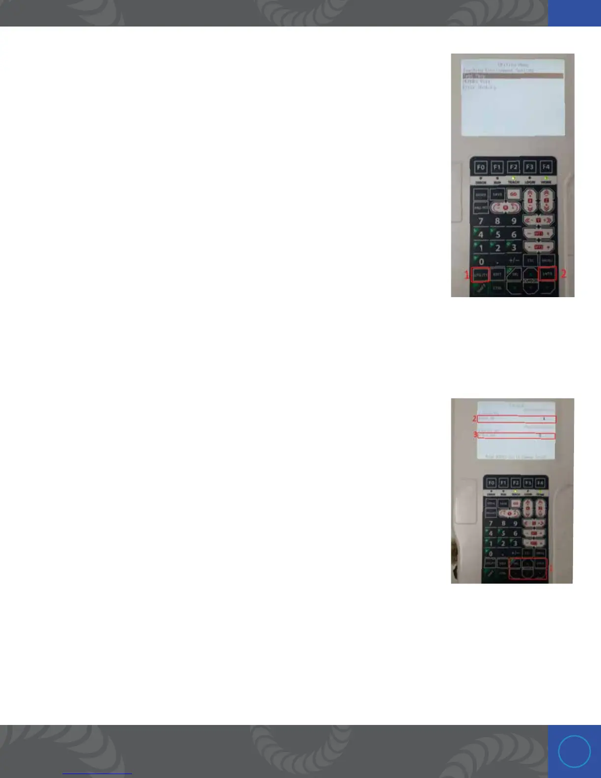
is screen displays and give access to all the PLC inputs and outputs.
1. e cursor buttons can be used move around this screen and the “ENTR” button
can be used to trigger the outputs.
2. e “I/0-1 IN” line has 8 spaces, and the 3rd from the left should display “1.”
is indicates that the welder is ready to weld (the play button is pressed and the
welder is ready to weld). Repeatably pressing the “Play” button on the welder will
make the “1” appear and dissappear. Put the welder in “Play” (make sure the “1” is
visible).
e 1st space from the left on the “I/O-1 IN” line indicates that a weld has
occurred and it was good. Since we have not made a weld yet, this first space
should be blank.
3. e “I/0-1 OUT” line has 8 spaces. Move the cursor to the 1st space from the left. is output is used to
trigger a weld on the welder.
2. With the cursor in the 1st position from the left on the “I/O-1 OUT” line, press the “ENTR” button to
trigger a weld manually.
 Loading...