Installation
General instructions
IG-136-EN version 10; 23/06/2016
27
cgm.3 system
Fully SF6 gas insulated medium voltage switchgear up to 40.5 kV in accordance with IEC Standards
Figure 4.12 Removing the cable compartment cover
3. Anchor the first cubicle to the floor of the installation
using M10 bolts at the points prepared in its base.
This will prevent displacements or vibrations due to
causes such as short-circuiting, flooding, etc. The
following levels and figures should be taken into
account:
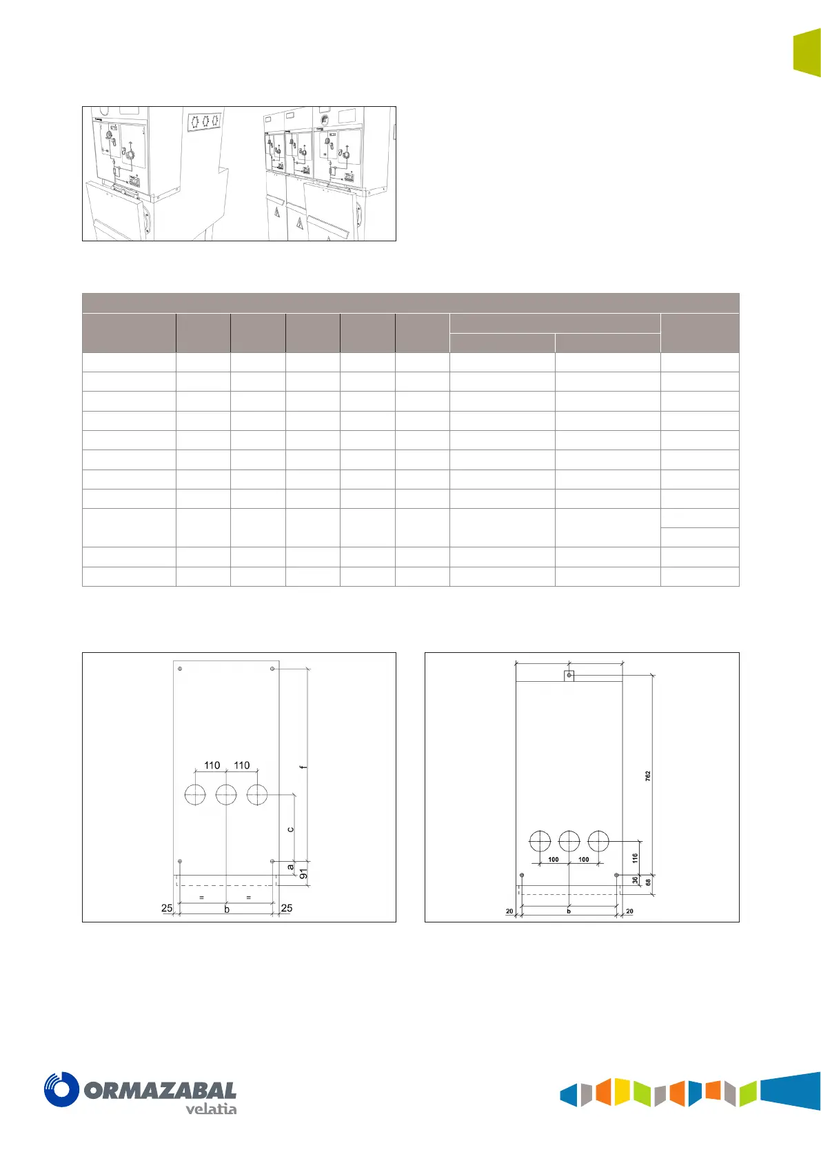
Anchoring dimensions [mm]
Module a b c d e
f
g
Internal arc 0.5 s Internal arc 1 s
l
50 368 245 - - 540 710 -
s
50 368 - - - 540 710 -
s-pt
50 550 - - - 540 710 -
p
50 430 60 - - 540 710 -
v
50 550 325 - - 540 710 -
rb
50 368 245 - - 540 710 -
rb-pt
50 368 245 - - 540 710 -
m
35 1030* 235 - - 1030 1030 -
rc
50 317 435 - - 540 710
-rci 209
-rcd 158
2lp
50 368 245 430 418 540 710 60
2lv
50 550 325 418 - - 710 60
(*) Separation between anchors for 1100 mm wide cubicles; separation of 830 mm for 900 mm wide cubicles.
Figure 4.13
Anchoring points in cgm.3. -l, -s, -s-pt, -p,-v, -rb, -rb-pt
cubicles of 1745 mm high
Figure 4.14 Anchoring points in cgm.3 -l, -p, -v cubicles of
1400 mm high