orolia.com EdgeSync Manual rev 1 | 23
Interface :: ToD/1PPS Output
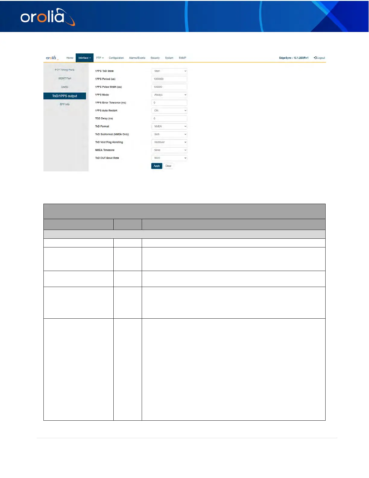
Figure 12 Interface :: ToD / 1PPS Output
The ToD / 1PPS Output webpage contains the following selections, entries, and buttons:
Interface :: ToD / 1PPS Output
Legend: RO = Read Only, RW = Read/Write, WO = Write Only
Stop/Start control of 1PPS output
1PPS pulse period in micro-seconds. Typically, one second but
can be configured to be different.
Range: 1000000 to 4294967295 (or ~ 1hour)
1PPS pulse width in micro-seconds.
Range: 250 to (1PPS Period minus 250)
Sync,
Holdover,
(ns)
Range: 0 to 4294967295
• If the 1PPS mode is Always, the Error Tolerance is simply
ignored.
For Sync and Holdover modes, the
error tolerance has the following effects:
• If the Error Tolerance is zero, then the ToD/1PPS signal is
started/stopped as soon as the MCE enters/leaves
corresponding Sync/Holdover states.
• If the Error Tolerance is non-zero, and the MCE is in the
Holdover state, the ToD/1PPS signal is stopped as soon as either
the estimated error becomes larger than the Error Tolerance or
the MCE exits the Holdover state.