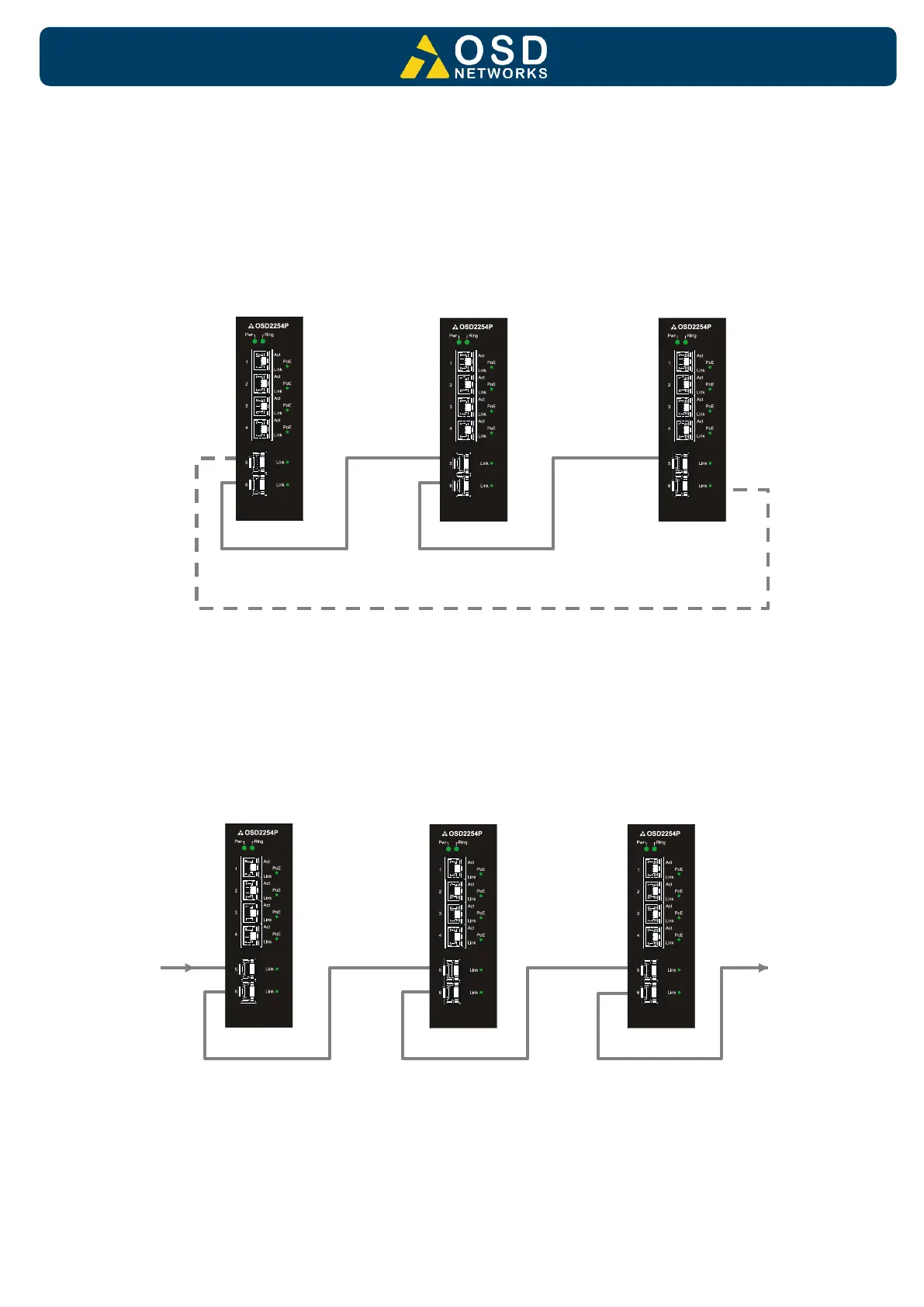
To connect the OSD2254EP in a redundant ring configuration ports 5 and 6 must be used
together with fiber SFPs. The non-ring ports (ports 1,2,3 & 4) should be used to connect to
your Ethernet devices (eg. Cameras, PLCs, computers, etc.)
Figure 15 shows the connection method. Typically, the SFP used would be a fiber SFP with
duplex LC connectors. The dashed line indicates the closed loop, but more OSD2254EP units
can be connected to the ring as required using this topology. Ensure that the switch settings
for port 5 and 6 are set to 1000Mbps (1Gbps) – see Table 5. Note: connection diagram is for
illustrative purposes only. Port 5/6 can be connected in to either port to achieve redundant
ring configuration.
FIGURE 15: REDUNDANT RING CONNECTION
Bus Operation
To connect the OSD2254EP in a bus configuration ports 5 and 6 must be used together with
fiber SFPs. The remaining ports (ports 1,2,3 & 4) should be used to connect to your Ethernet
devices (eg. Cameras, PLCs, computers, etc.)
FIGURE 16: BUS CONNECTION
 Loading...