14
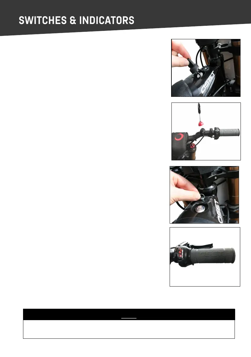
KEY SWITCH
The key switch turns the power on and o. When the rider is sing
on the bike, this is located in front of them above the tank cover.
The key is removable, and should be removed when the bike is not
in use.
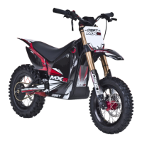
KILL SWITCH
This switch is in addion to the key switch and provides extra func-
onality. To enter the on posion place magnec top cap on base.
The key switch MUST be in the ‘on’ posion for the magnec kill
switch to operate.
With the key switch in the ‘on’ posion, the kill switch can be used to
turn the bike on by simply connecng the red magnec cap to the
black base on the handlebar, to turn the bike o using the kill switch
remove the magnec red cap from the black base on the handlebar.
As a safety precauon, if the throle is applied before the kill switch
is connected, the bike will not move.
Always ensure the rider is wearing the kill switch around their wrist
and that the cord is ghtened rmly.
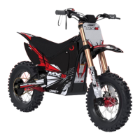
DIAL PANEL REMOVAL
The bike’s adjustment dials are located beneath the small black panel
which also houses the key switch.
To remove the panel, twist the fastener and li the front of the
panel up and towards the handlebars.
The baery charge indicator is located on the throle assembly and
shows the state of the baeries. The indicator lights can be checked
at any me to determine if the main power is o or on. Always turn
the power o and remove the key when the bike is not in use.
NOTE
Now your OSET is fully assembled, adjusted and checked. Once the baeries are fully
charged, your OSET will be ready to ride safely.
CHARGE INDICATOR