R
Ryan GomezAug 2, 2025
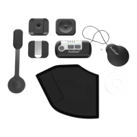
How to fix Otto Bock Fitness Equipment when I do not get a foot lift at every step?
- GGrace JamesAug 2, 2025
If you're not getting a foot lift at every step with your Otto Bock Fitness Equipment, ensure the Control Unit is switched on. Also, check that the stimulation intensity is high enough. Verify the Antenna is correctly placed in the Antenna Fixture above the Implant and that the Antenna cable is intact without sharp bends. Confirm the Heel Switch is correctly placed under your heel inside the Heel Sock and check the connection between the Heel Switch and the Control Unit. Test the Heel Switch by pressing it with your fingers. If the Control Unit doesn't respond with light/audio signals, check the battery status of the Heel Switch and Control Unit, repeat pairing, or replace the Heel Switch. If the Control Unit does respond, check that the Antenna plug is properly connected.